USB通信 ![]()
![]()
■ PIC18F4550-PC 間 CDCクラス通信
( 自作キバン + Microchip社デモソフト:Basic Demo)
マイクロチップDemoBoard(PICDEM FS USB DM163025)($59.99ドル)相当の自作キバンによるUSB通信を行なったので紹介します。
USBフレームワークMCHPFSUSB Framework 2.3にはPICDEMでそのまま動作するPIC側ソフトとPC側ソフト(VB、C++、C#)がサンプルソフトとして
公開されています。PICDEMに対しての変更は下記のみで付属のUSBフレームワークMCHPFSUSB Framework 2.3付属のCDCクラスサンプル
ソフトがそのまま動くようにしました.。 →PC側ソフト(VC#)
→PC側ソフト(VC++)
① PIC : PIC18F4550(TQFP) → PIC18F4550(PDIP)
② USBバス電源、ボード電源切り替え回路簡略化
<試作品仕様>(PICDEMボードと全く同じです)
① 自作キバン(自給電源有)のUSBコネクタ(B type)にPCからのUSBケーブルを接続すると、USBドライバーがインストールされる。
② USBバス電源かボード電源が供給されると、発光ダイオードD1,D2が交互に点滅する。
③ PC側ダイアログウィンドウで通信するCOMポートをコンボボックスから選択する。
④ Connect ボタンをクリックして、自作ボードとUSB接続を行なう。 USB通信が可能な状態になるとエディットボックスに Conected
の
表示がでる。
⑤ 自作PIC側ボード上のスイッチSW2を押すと、自作PIC側ボードから Button Pressed -- の文字がUSB通信で送信され PC画面上
ダイアログボックスのエディットボックスに表示される。
⑥ PC画面上ダイアログボックスのテキストボックスに英数字をキーインして SendData ボタンをクリックすると自作PIC側ボードへこの
文字が送信される。
⑦ PIC側で受信文字に1を加え(ASCIIコードが1つ繰り上がる)、PC側に返信する。
⑧ PC側では受信した文字を表示する。
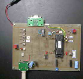
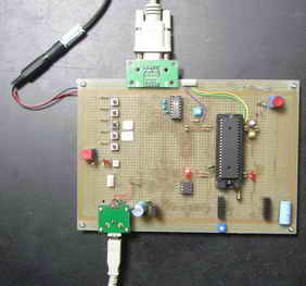
<試作品回路図> (→回路図のPDFファイル)
PIC18F4550をつかった場合の回路図を以下に示します。
<試作品外観>下記の写真には上記回路図にはない、また本テーマと関係のない部品が多々写っています
//<プログラム例> コンパイラC18 →PC側ソフト(VC#)
→PC側ソフト(VC++)
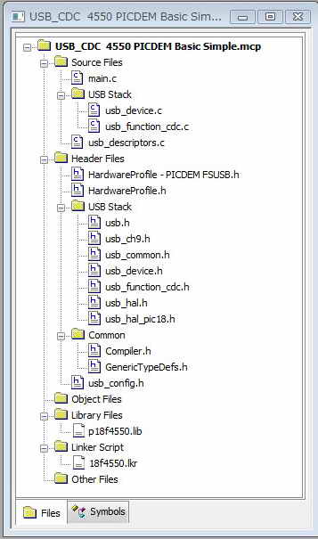
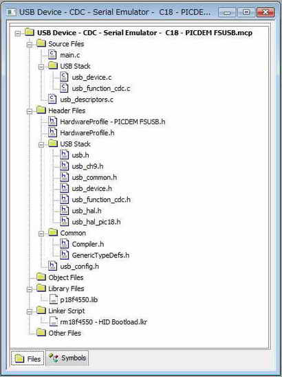
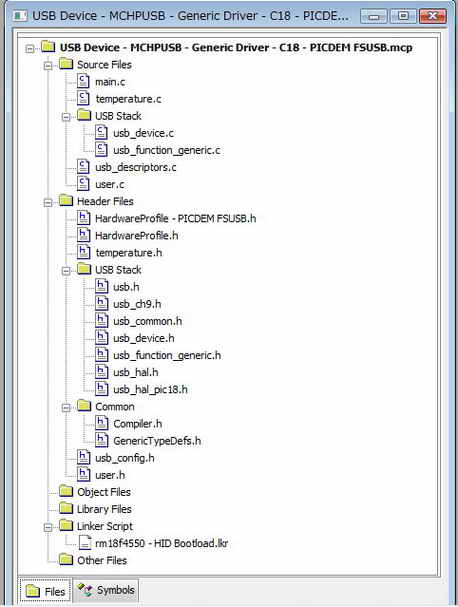
以下のプログラムは マイクロチップ社のMCHPFSUSB Framework 2.3をダウンロードして解凍後PCにできる…\Microchip Solutions\
USB Device - CDC - Basic Demo\CDC - Basic Demo - Firmwareフォルダに収納されているプロジェクトファイル
USB Device - CDC - Basic Demo - C18 - PICDEM FSUSB.mcpに含まれているファイルの抜粋です。プログラム生成に際し関係するファイルは
下記のに示すようにたくさんあります。 以下の内容記載ファイルは、 ユーザープログラムを作成する際に変更する必要がある4つのファイルです。
ファイル内のコメントの削除、変更 及び追加はおこなっていますがソースコードの変更はしていません。
① main.c
② usb_config.h
③ usb_descriptors.c
④ HardwareProfile.h
// ファイル構成
//---   main.c  ------------------------------------------------

#include <p18f4550.h>
#include "GenericTypeDefs.h"
#include "Compiler.h"
#include "./USB/usb_device.h"
#include "./USB/usb.h"
#include "./USB/usb_function_cdc.h"

#include "usb_config.h"
#include "HardwareProfile.h"

        #pragma config PLLDIV   = 5         // (20 MHz crystal on PICDEM FS USB board)
        #pragma config CPUDIV   = OSC1_PLL2
        #pragma config USBDIV   = 2         // Clock source from 96MHz PLL/2
        #pragma config FOSC     = HSPLL_HS      //システムクロック:20MHz
        #pragma config FCMEN    = OFF
        #pragma config IESO     = OFF
        #pragma config PWRT     = OFF
        #pragma config BOR      = ON
        #pragma config BORV     = 3
        #pragma config VREGEN   = ON      //USB Voltage Regulator
        #pragma config WDT      = OFF
        #pragma config WDTPS    = 32768
        #pragma config MCLRE    = ON
        #pragma config LPT1OSC  = OFF
        #pragma config PBADEN   = OFF
//      #pragma config CCP2MX   = ON
        #pragma config STVREN   = ON
        #pragma config LVP      = OFF
//      #pragma config ICPRT    = OFF       // Dedicated In-Circuit Debug/Programming
        #pragma config XINST    = OFF       // Extended Instruction Set
        #pragma config CP0      = OFF
        #pragma config CP1      = OFF
//      #pragma config CP2      = OFF
//      #pragma config CP3      = OFF
        #pragma config CPB      = OFF
//      #pragma config CPD      = OFF
        #pragma config WRT0     = OFF
        #pragma config WRT1     = OFF
//      #pragma config WRT2     = OFF
//      #pragma config WRT3     = OFF
        #pragma config WRTB     = OFF       // Boot Block Write Protection
        #pragma config WRTC     = OFF
//      #pragma config WRTD     = OFF
        #pragma config EBTR0    = OFF
        #pragma config EBTR1    = OFF
//      #pragma config EBTR2    = OFF
//      #pragma config EBTR3    = OFF
        #pragma config EBTRB    = OFF


char USB_In_Buffer[64];
char USB_Out_Buffer[64];
BOOL stringPrinted;


static void InitializeSystem(void);
void ProcessIO(void);
void USBDeviceTasks(void);
void YourHighPriorityISRCode();
void YourLowPriorityISRCode();
void BlinkUSBStatus(void);
void UserInit(void);


int main(void)
{
    InitializeSystem();

    while(1)
    {
                USBDeviceTasks();//ポーリングチェック
                ProcessIO();
    }
        return 0;
}

static void InitializeSystem(void)      //システム初期化
{
    #if defined(USE_USB_BUS_SENSE_IO)   // USBバス電圧検出 : オプション
    tris_usb_bus_sense = INPUT_PIN; // USBバス電圧検出    IOピンは HardwareProfile.hで設定されている。
        #endif

    #if defined(USE_SELF_POWER_SENSE_IO)        //セルフ電圧検出 : オプション
    tris_self_power = INPUT_PIN;        // IOピンは HardwareProfile.h で設定されている
    #endif                                                      //ホスト(PC)からのGetStatus要求があった場合デバイスは現状がセルフパワーかバスパワー回答の必要あり

    USBDeviceInit();    //usb_device.c.  Initializes USB module SFRs and firmware
                                        //variables to known states.
    UserInit();

}

void UserInit(void)     //ユーザ初期化
{
    stringPrinted = TRUE;
    //Initialize all of the LED pins

        mInitAllLEDs();
}//end UserInit


void ProcessIO(void)    //ユーザが処理する部分
{
    BYTE numBytesRead;

    //Blink the LEDs according to the USB device status
    BlinkUSBStatus();
    // User Application USB tasks
    if((USBDeviceState < CONFIGURED_STATE)||(USBSuspendControl==1)) return;

    if(sw2 == 0)
    {
        if(stringPrinted == FALSE)
        {
            if(mUSBUSARTIsTxTrfReady())
            {
                putrsUSBUSART("Button Pressed -- \r\n");
                stringPrinted = TRUE;
            }
        }
        mLED_3_On();
    }
    else
    {
        stringPrinted = FALSE;
        mLED_3_Off();
    }

    if(mUSBUSARTIsTxTrfReady())
    {
                numBytesRead = getsUSBUSART(USB_Out_Buffer,64);
                if(numBytesRead != 0)
                {
                        BYTE i;

                        for(i=0;i<numBytesRead;i++)
                        {
                                switch(USB_Out_Buffer[i])
                                {
                                        case 0x0A:
                                        case 0x0D:
                                                USB_In_Buffer[i] = USB_Out_Buffer[i];
                                                break;
                                        default:
                                                USB_In_Buffer[i] = USB_Out_Buffer[i] + 1;
                                                break;
                                }
                        }
                        putUSBUSART(USB_In_Buffer,numBytesRead);
                }
        }

    CDCTxService();
}               //end ProcessIO


void BlinkUSBStatus(void)               //LED点滅制御
{
    static WORD led_count=0;

    if(led_count == 0)led_count = 10000U;
    led_count--;

    #define mLED_Both_Off()         {mLED_1_Off();mLED_2_Off();}
    #define mLED_Both_On()          {mLED_1_On();mLED_2_On();}
    #define mLED_Only_1_On()        {mLED_1_On();mLED_2_Off();}
    #define mLED_Only_2_On()        {mLED_1_Off();mLED_2_On();}

    if(USBSuspendControl == 1)
    {
        if(led_count==0)
        {
            mLED_1_Toggle();
            if(mGetLED_1())
            {
                mLED_2_On();
            }
            else
            {
                mLED_2_Off();
            }
        }//end if
    }
    else
    {
        if(USBDeviceState == DETACHED_STATE)
        {
            mLED_Both_Off();
        }
        else if(USBDeviceState == ATTACHED_STATE)
        {
            mLED_Both_On();
        }
        else if(USBDeviceState == POWERED_STATE)
        {
            mLED_Only_1_On();
        }
        else if(USBDeviceState == DEFAULT_STATE)
        {
            mLED_Only_2_On();
        }
        else if(USBDeviceState == ADDRESS_STATE)
        {
            if(led_count == 0)
            {
                mLED_1_Toggle();
                mLED_2_Off();
            }//end if
        }
        else if(USBDeviceState == CONFIGURED_STATE)
        {
            if(led_count==0)
            {
                mLED_1_Toggle();
                if(mGetLED_1())
                {
                    mLED_2_Off();
                }
                else
                {
                    mLED_2_On();
                }
            }//end if
        }//end if(...)
    }//end if(UCONbits.SUSPND...)

}//end BlinkUSBStatus


// ************** USB Callback Functions : USBCBxxx()*******************************

void USBCBSuspend(void) //サスペンドモードになるとき設定すべきことを書く関数   ピンの低消費電力化etc
{
}
//----------------------------------------------------------------------------------
void USBCBWakeFromSuspend(void) //サスペンドモードからの起動時に呼び出される関数
{
}
//----------------------------------------------------------------------------------
void USBCB_SOF_Handler(void)    //この関数は SOFパケットと同期して呼び出される。フルスピードであれば1msec毎によびだされる。
{                                                               //必要があればアプリケーションで使用してもよい
}
//-----------------------------------------------------------------------------
void USBCBErrorHandler(void)    //開発段階でのデバック時エラーなどで呼び出される
{
}
//-----------------------------------------------------------------------------------
void USBCBCheckOtherReq(void)//ホスト(PC)からのSSETUP要求が来た場合によびだされる。
{
    USBCheckCDCRequest();
}
//----------------------------------------------------------------------------------
void USBCBStdSetDscHandler(void)        //SET_DESCRIPTOR要求がきた場合にこの関数は呼び出される。
{                                                                       //ほとんどのアプリケーションでは使われることはない
}
//---------------------------------------------------------------------------------
void USBCBInitEP(void)//ホスト(PC)からSET_CONFIGURATION 要求がきた場合にこの関数はよびだされる。
{                                       //デバイスの現状に合わせ初期化される。
    CDCInitEP();
}
//-----------------------------------------------------------------------------------
void USBCBSendResume(void)              // ホスト(PC)ウェイク待ち時間設定
{
    static WORD delay_count;
    USBResumeControl = 1;                // Start RESUME signaling
    delay_count = 1800U;                // Set RESUME line for 1-13 ms
    do
    {
        delay_count--;
    }while(delay_count);
    USBResumeControl = 0;
}
//--------------------------------------------------------------------------------------
void USBCBEP0DataReceived(void) //この関数は、エンドポイント0のデータを受信した場合に呼び出される。
{
}

//********************************************************************************************************
//********************************************************************************************************
//********************************************************************************************************
//--  usb_config.h  ------------------------------------------------------------------------

//USBコンフィグレーション設定

#ifndef USBCFG_H
#define USBCFG_H


#define USB_EP0_BUFF_SIZE       8       // エンドポイント0のバッファーサイズ設定: 8, 16, 32, or 64 bytes.
                                                                // Using larger options take more SRAM, but
                                                                // does not provide much advantage in most types
                                                                // of applications.  Exceptions to this, are applications
                                                                // that use EP0 IN or OUT for sending large amounts of
                                                                // application related data.

#define USB_MAX_NUM_INT         1   // 内蔵インターフェースの最大数を設定

//Device descriptor - if these two definitions are not defined then
//  a ROM USB_DEVICE_DESCRIPTOR variable by the exact name of device_dsc
//  must exist.
#define USB_USER_DEVICE_DESCRIPTOR &device_dsc
#define USB_USER_DEVICE_DESCRIPTOR_INCLUDE extern ROM USB_DEVICE_DESCRIPTOR device_dsc

//Configuration descriptors - if these two definitions do not exist then
//  a ROM BYTE *ROM variable named exactly USB_CD_Ptr[] must exist.
#define USB_USER_CONFIG_DESCRIPTOR USB_CD_Ptr
#define USB_USER_CONFIG_DESCRIPTOR_INCLUDE extern ROM BYTE *ROM USB_CD_Ptr[]

//Make sure only one of the below "#define USB_PING_PONG_MODE"
//is uncommented.
//#define USB_PING_PONG_MODE USB_PING_PONG__NO_PING_PONG
#define USB_PING_PONG_MODE USB_PING_PONG__FULL_PING_PONG
//#define USB_PING_PONG_MODE USB_PING_PONG__EP0_OUT_ONLY
//#define USB_PING_PONG_MODE USB_PING_PONG__ALL_BUT_EP0         //NOTE: This mode is not supported in PIC18F4550 family rev A3 devices


#define USB_POLLING

/* Parameter definitions are defined in usb_device.h */
#define USB_PULLUP_OPTION USB_PULLUP_ENABLE
//                        USB_PULLUP_DISABLE

#define USB_TRANSCEIVER_OPTION USB_INTERNAL_TRANSCEIVER
//                             USB_EXTERNAL_TRANSCEIVER

#define USB_SPEED_OPTION USB_FULL_SPEED
//                       USB_LOW_SPEED (not valid option for PIC24F devices)

#define USB_NUM_STRING_DESCRIPTORS 3

/** DEVICE CLASS USAGE *********************************************/
#define USB_SUPPORT_DEVICE
#define USB_USE_CDC

/** ENDPOINTS ALLOCATION *******************************************/
#define USB_MAX_EP_NUMBER           3

/* CDC */
#define CDC_COMM_INTF_ID        0x0
#define CDC_COMM_EP              2
#define CDC_COMM_IN_EP_SIZE      8

#define CDC_DATA_INTF_ID        0x01
#define CDC_DATA_EP             3
#define CDC_DATA_OUT_EP_SIZE    64
#define CDC_DATA_IN_EP_SIZE     64

//#define USB_CDC_SUPPORT_ABSTRACT_CONTROL_MANAGEMENT_CAPABILITIES_D2 //Send_Break command
#define USB_CDC_SUPPORT_ABSTRACT_CONTROL_MANAGEMENT_CAPABILITIES_D1 //Set_Line_Coding, Set_Control_Line_State, Get_Line_Coding, and Serial_State commands
/** DEFINITIONS ****************************************************/

#endif //USBCFG_H

//********************************************************************************************************
//********************************************************************************************************
//********************************************************************************************************
//--- usb_descriptors.c------------


//----デスクリプタの設定----------
#ifndef __USB_DESCRIPTORS_C
#define __USB_DESCRIPTORS_C

/** INCLUDES *******************************************************/
#include "GenericTypeDefs.h"
#include "Compiler.h"
#include "usb_config.h"
#include "./USB/usb.h"
#include "./USB/usb_function_cdc.h"

/** CONSTANTS ******************************************************/
#if defined(__18CXX)
#pragma romdata
#endif

/* Device Descriptor */
ROM USB_DEVICE_DESCRIPTOR device_dsc=
{
    0x12,                   // Size of this descriptor in bytes
    USB_DESCRIPTOR_DEVICE,  // DEVICE descriptor type
    0x0200,                 // USB Spec Release Number in BCD format    //TODO: workaround for BSTALL erratum
    CDC_DEVICE,             // Class Code
    0x00,                   // Subclass code
    0x00,                   // Protocol code
    USB_EP0_BUFF_SIZE,      // Max packet size for EP0, see usb_config.h
    0x4D8,                  // ★ Vender ID
    0x000A,                 // ★ Product ID: CDC RS-232 Emulation Demo
    0x0001,                 // Device release number in BCD format
    0x01,                   // Manufacturer string index
    0x02,                   // Product string index
    0x00,                   // Device serial number string index
    0x01                    // Number of possible configurations
};

/* Configuration 1 Descriptor */
ROM BYTE configDescriptor1[]={
    /* Configuration Descriptor */
    0x09,//sizeof(USB_CFG_DSC),    // Size of this descriptor in bytes
    USB_DESCRIPTOR_CONFIGURATION,                // CONFIGURATION descriptor type
    67,0,                   // Total length of data for this cfg
    2,                      // Number of interfaces in this cfg
    1,                      // Index value of this configuration
    0,                      // Configuration string index
    _DEFAULT | _SELF,               // Attributes, see usb_device.h
    50,                     // Max power consumption (2X mA)

    /* Interface Descriptor */
    9,//sizeof(USB_INTF_DSC),   // Size of this descriptor in bytes
    USB_DESCRIPTOR_INTERFACE,               // INTERFACE descriptor type
    0,                      // Interface Number
    0,                      // Alternate Setting Number
    1,                      // Number of endpoints in this intf
    COMM_INTF,              // Class code
    ABSTRACT_CONTROL_MODEL, // Subclass code
    V25TER,                 // Protocol code
    0,                      // Interface string index

    /* CDC Class-Specific Descriptors */
    sizeof(USB_CDC_HEADER_FN_DSC),
    CS_INTERFACE,
    DSC_FN_HEADER,
    0x10,0x01,

    sizeof(USB_CDC_ACM_FN_DSC),
    CS_INTERFACE,
    DSC_FN_ACM,
    USB_CDC_ACM_FN_DSC_VAL,

    sizeof(USB_CDC_UNION_FN_DSC),
    CS_INTERFACE,
    DSC_FN_UNION,
    CDC_COMM_INTF_ID,
    CDC_DATA_INTF_ID,

    sizeof(USB_CDC_CALL_MGT_FN_DSC),
    CS_INTERFACE,
    DSC_FN_CALL_MGT,
    0x00,
    CDC_DATA_INTF_ID,

    /* Endpoint Descriptor */
    //sizeof(USB_EP_DSC),DSC_EP,_EP02_IN,_INT,CDC_INT_EP_SIZE,0x02,
    0x07,/*sizeof(USB_EP_DSC)*/
    USB_DESCRIPTOR_ENDPOINT,    //Endpoint Descriptor
    _EP02_IN,            //EndpointAddress
    _INTERRUPT,                       //Attributes
    0x08,0x00,                  //size
    0x02,                       //Interval

    /* Interface Descriptor */
    9,//sizeof(USB_INTF_DSC),   // Size of this descriptor in bytes
    USB_DESCRIPTOR_INTERFACE,               // INTERFACE descriptor type
    1,                      // Interface Number
    0,                      // Alternate Setting Number
    2,                      // Number of endpoints in this intf
    DATA_INTF,              // Class code
    0,                      // Subclass code
    NO_PROTOCOL,            // Protocol code
    0,                      // Interface string index

    /* Endpoint Descriptor */
    //sizeof(USB_EP_DSC),DSC_EP,_EP03_OUT,_BULK,CDC_BULK_OUT_EP_SIZE,0x00,
    0x07,/*sizeof(USB_EP_DSC)*/
    USB_DESCRIPTOR_ENDPOINT,    //Endpoint Descriptor
    _EP03_OUT,            //EndpointAddress
    _BULK,                       //Attributes
    0x40,0x00,                  //size
    0x00,                       //Interval

    /* Endpoint Descriptor */
    //sizeof(USB_EP_DSC),DSC_EP,_EP03_IN,_BULK,CDC_BULK_IN_EP_SIZE,0x00
    0x07,/*sizeof(USB_EP_DSC)*/
    USB_DESCRIPTOR_ENDPOINT,    //Endpoint Descriptor
    _EP03_IN,            //EndpointAddress
    _BULK,                       //Attributes
    0x40,0x00,                  //size
    0x00,                       //Interval
};


//Language code string descriptor
ROM struct{BYTE bLength;BYTE bDscType;WORD string[1];}sd000={
sizeof(sd000),USB_DESCRIPTOR_STRING,{0x0409}};

//Manufacturer string descriptor
ROM struct{BYTE bLength;BYTE bDscType;WORD string[25];}sd001={
sizeof(sd001),USB_DESCRIPTOR_STRING,
{'M','i','c','r','o','c','h','i','p',' ',
'T','e','c','h','n','o','l','o','g','y',' ','I','n','c','.'
}};

//Product string descriptor
ROM struct{BYTE bLength;BYTE bDscType;WORD string[25];}sd002={
sizeof(sd002),USB_DESCRIPTOR_STRING,
{'C','D','C',' ','R','S','-','2','3','2',' ',
'E','m','u','l','a','t','i','o','n',' ','D','e','m','o'}
};

//Array of configuration descriptors
ROM BYTE *ROM USB_CD_Ptr[]=
{
    (ROM BYTE *ROM)&configDescriptor1
};
//Array of string descriptors
ROM BYTE *ROM USB_SD_Ptr[USB_NUM_STRING_DESCRIPTORS]=
{
    (ROM BYTE *ROM)&sd000,
    (ROM BYTE *ROM)&sd001,
    (ROM BYTE *ROM)&sd002
};

#pragma code
#endif
/** EOF usb_descriptors.c ****************************************************/


//********************************************************************************************************
//********************************************************************************************************
//********************************************************************************************************
//----------  HardwareProfile.h -------------

// 使うキバンのハード設定をしているヘッダーファイルをインクルードする。
#include "HardwareProfile - PICDEM FSUSB.h"

//----------------------------------------------------------------------
//-----------------------------------------------------------------
//----- HardwareProfile.h --------------------


//このファイルでDemoキバンのハードを設定

  //#define USE_SELF_POWER_SENSE_IO             //ボード電源検出をする場合はこの行を加える
                                                                                // → USE_SELF_POWER_SENSE_IO を定義する。
        #define tris_self_power     TRISAbits.TRISA2    // Input
    #if defined(USE_SELF_POWER_SENSE_IO)
    #define self_power          PORTAbits.RA2
    #else
    #define self_power          1
    #endif

    //#define USE_USB_BUS_SENSE_IO              //バス電源検出jをする場合はこの行を加える
                                                                                // → USE_USB_BUS_SENSE_IO
    #define tris_usb_bus_sense  TRISAbits.TRISA1    // Input
    #if defined(USE_USB_BUS_SENSE_IO)
    #define USB_BUS_SENSE       PORTAbits.RA1
    #else
    #define USB_BUS_SENSE       1
    #endif


    //Uncomment the following line to make the output HEX of this
    //  project work with the MCHPUSB Bootloader
    //#define PROGRAMMABLE_WITH_USB_MCHPUSB_BOOTLOADER  //MCHPブートローダーを使用する場合に定義する。

    //Uncomment the following line to make the output HEX of this
    //  project work with the HID Bootloader
    #define PROGRAMMABLE_WITH_USB_HID_BOOTLOADER        //HIDブートローダーを使用する場合に定義する。


    #define DEMO_BOARD PICDEM_FS_USB
    #define PICDEM_FS_USB
    #define CLOCK_FREQ 48000000


    //-- LEDの点灯制御関係のポートと定数設定--------------------------
    #define mInitAllLEDs()      LATD &= 0xF0; TRISD &= 0xF0;

    #define mLED_1              LATDbits.LATD0
    #define mLED_2              LATDbits.LATD1
    #define mLED_3              LATDbits.LATD2
    #define mLED_4              LATDbits.LATD3

    #define mGetLED_1()         mLED_1
    #define mGetLED_2()         mLED_2
    #define mGetLED_3()         mLED_3
    #define mGetLED_4()         mLED_4

    #define mLED_1_On()         mLED_1 = 1;
    #define mLED_2_On()         mLED_2 = 1;
    #define mLED_3_On()         mLED_3 = 1;
    #define mLED_4_On()         mLED_4 = 1;

    #define mLED_1_Off()        mLED_1 = 0;
    #define mLED_2_Off()        mLED_2 = 0;
    #define mLED_3_Off()        mLED_3 = 0;
    #define mLED_4_Off()        mLED_4 = 0;

    #define mLED_1_Toggle()     mLED_1 = !mLED_1;
    #define mLED_2_Toggle()     mLED_2 = !mLED_2;
    #define mLED_3_Toggle()     mLED_3 = !mLED_3;
    #define mLED_4_Toggle()     mLED_4 = !mLED_4;

    //----- スイッチ制御のポートと定数設定----------------------
   #define mInitAllSwitches()  TRISBbits.TRISB4=1;TRISBbits.TRISB5=1;
    #define mInitSwitch2()      TRISBbits.TRISB4=1;
    #define mInitSwitch3()      TRISBbits.TRISB5=1;
    #define sw2                 PORTBbits.RB4
    #define sw3                 PORTBbits.RB5
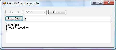
<動作結果>
① COM8ポートを選択して Connectボタンをクリックすると Connected が表示されます。
② キバン上のスイッチSW2を押すと 文字列 Button Pressed-- が送信されてきます。
③ 5をキーインして Send Data ボタンをクリックすると 6が送られてきます。
■ PIC18F4550-PC 間 CDCクラス通信
( 自作キバン + Microchip社デモソフト:Serial Emulator)
マイクロチップDemoBoard(PICDEM FS USB DM163025)($59.99ドル)相当の自作キバンによるUSB通信を行なったので紹介します。
USBフレームワークMCHPFSUSB Framework 2.3にはPICDEMでそのまま動作するPIC側ソフトとPC側ソフト(VB、C++、C#)がサンプルソフトとして
付属しています。PICDEMに対しての変更は下記のみで付属のUSBフレームワークMCHPFSUSB Framework 2.3付属のCDCクラスサンプル
ソフトがそのまま動くようにしました。 →PC側ソフト(VC#)
→PC側ソフト(VC++)
① PIC : PIC18F4550(TQFP) → PIC18F4550(PDIP)
② USBバス電源、ボード電源切り替え回路簡略化
USBフレームワークMCHPFSUSB Framework 2.3 に付属しているCDCクラス通信のサンプルソフトに以下のようなリモートエコーバックものが
あります。
<試作品仕様>
① PC側ダイアログからキーインした文字列を USBケーブル経由で自作PICキバン側で受信する。
② 受信した文字列を RS232Cケーブル経由でPC側に返信する。
③ PC側では 受信した文字列を通信ソフトTeraTerm に表示する。
<試作品回路図> (→回路図のPDFファイル)
PIC18F4550をつかった場合の回路図を以下に示します。
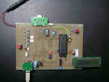
<試作品外観>下記の写真には上記回路図にはない、また本テーマと関係のない部品が多々写っています
<プログラム例> コンパイラC18 →PC側ソフト(VC#)
→PC側ソフト(VC++)
 以下のプログラムはマイクロチップ社のMCHPFSUSB Framework 2.3をダウンロードして解凍後PCにできる…\Microchip Solutions\
USB Device - CDC - Basic Demo\CDC - Basic Demo - Firmwareフォルダに収納されているプロジェクトファイル
USB Device - CDC - Serial Emulator -  C18 - PICDEM FSUSB.mcpに含まれているファイルの抜粋です。プログラム生成に際し
関係するファイルは下記のに示すようにたくさんあります。 以下の内容記載ファイルは、 ユーザープログラムを作成する際に
変更する必要がある4つのファイルです。ファイル内のコメントの削除、変更 及び追加はおこなっていますがソースコードの
変更はしていません。
 ① main.c
 ② usb_config.h
 ③ usb_descriptors.c
 ④ HardwareProfile.h
//液晶付 USB #include <p18f4550.h> #include <stdio.h> #include <delays.h> #include <stdio.h> #include <stdlib.h> #include "GenericTypeDefs.h" #include "Compiler.h" #include "./USB/usb_device.h" #include "./USB/usb.h" #include "./USB/usb_function_cdc.h" #include "usb_config.h" #include "HardwareProfile.h" #pragma config PLLDIV = 5 // (20 MHz crystal on PICDEM FS USB board) #pragma config CPUDIV = OSC1_PLL2 //システムクロック:20MHz (= 20MHz ÷ 1) #pragma config USBDIV = 2 // Clock source from 96MHz PLL/2 #pragma config FOSC = HSPLL_HS #pragma config FCMEN = OFF #pragma config IESO = OFF #pragma config PWRT = OFF #pragma config BOR = ON #pragma config BORV = 3 #pragma config VREGEN = ON //USB Voltage Regulator #pragma config WDT = OFF #pragma config WDTPS = 32768 #pragma config MCLRE = ON #pragma config LPT1OSC = OFF #pragma config PBADEN = OFF // #pragma config CCP2MX = ON #pragma config STVREN = ON #pragma config LVP = OFF // #pragma config ICPRT = OFF // Dedicated In-Circuit Debug/Programming #pragma config XINST = OFF // Extended Instruction Set #pragma config CP0 = OFF #pragma config CP1 = OFF // #pragma config CP2 = OFF // #pragma config CP3 = OFF #pragma config CPB = OFF // #pragma config CPD = OFF #pragma config WRT0 = OFF #pragma config WRT1 = OFF // #pragma config WRT2 = OFF // #pragma config WRT3 = OFF #pragma config WRTB = OFF // Boot Block Write Protection #pragma config WRTC = OFF // #pragma config WRTD = OFF #pragma config EBTR0 = OFF #pragma config EBTR1 = OFF // #pragma config EBTR2 = OFF // #pragma config EBTR3 = OFF #pragma config EBTRB = OFF char USB_Out_Buffer[CDC_DATA_OUT_EP_SIZE]; char RS232_Out_Data[CDC_DATA_IN_EP_SIZE]; unsigned char NextUSBOut; unsigned char NextUSBOut; //char RS232_In_Data; unsigned char LastRS232Out; // Number of characters in the buffer unsigned char RS232cp; // current position within the buffer unsigned char RS232_Out_Data_Rdy = 0; USB_HANDLE lastTransmission; static void InitializeSystem(void); void ProcessIO(void); void USBDeviceTasks(void); void YourHighPriorityISRCode(); void YourLowPriorityISRCode(); void BlinkUSBStatus(void); void UserInit(void); void InitializeUSART(void); void putcUSART(char c); unsigned char getcUSART (); void main(void) { InitializeSystem(); while(1) { USBDeviceTasks(); ProcessIO(); } } static void InitializeSystem(void) //システム初期化 { #if defined(USE_USB_BUS_SENSE_IO) tris_usb_bus_sense = INPUT_PIN; // USBバス電源検出をしない場合はこの行をコメントアウト See HardwareProfile.h #endif #if defined(USE_SELF_POWER_SENSE_IO) tris_self_power = INPUT_PIN; // ボード電源を検出しない場合はこの行をコメントアウト See HardwareProfile.h #endif USBDeviceInit(); //usb_device.c. Initializes USB module SFRs and firmware //variables to known states. UserInit(); } void UserInit(void) { unsigned char i; InitializeUSART(); for (i=0; i<sizeof(USB_Out_Buffer); i++) //USB バッファー初期化 { USB_Out_Buffer[i] = 0; } NextUSBOut = 0; LastRS232Out = 0; lastTransmission = 0; mInitAllLEDs(); } void InitializeUSART(void) //UART初期化 { unsigned char c; UART_TRISRx=1; // RX UART_TRISTx=0; // TX TXSTA = 0x24; // TX enable BRGH=1 RCSTA = 0x90; // Single Character RX SPBRG = 0x71; SPBRGH = 0x02; // 0x0271 for 48MHz -> 19200 baud BAUDCON = 0x08; // BRG16 = 1 c = RCREG; // read } #define mDataRdyUSART() PIR1bits.RCIF #define mTxRdyUSART() TXSTAbits.TRMT void putcUSART(char c) //USART送信 { TXREG = c; } #if defined(USB_CDC_SET_LINE_CODING_HANDLER) void mySetLineCodingHandler(void) //通信条件設定 { //If the request is not in a valid range if(cdc_notice.GetLineCoding.dwDTERate.Val > 115200) //115200bps以上のボーレートが設定された場合 { } else { DWORD_VAL dwBaud; CDCSetBaudRate(cdc_notice.GetLineCoding.dwDTERate.Val);//CDCドライバーに於ける、ボーレート設定 dwBaud.Val = (GetSystemClock()/4)/line_coding.dwDTERate.Val-1; //UART設定 SPBRG = dwBaud.v[0]; SPBRGH = dwBaud.v[1]; } } #endif unsigned char getcUSART () //USART受信 { char c; if (RCSTAbits.OERR) // in case of overrun error { // we should never see an overrun error, but if we do, RCSTAbits.CREN = 0; // reset the port c = RCREG; RCSTAbits.CREN = 1; // and keep going. } else c = RCREG; // not necessary. EUSART auto clears the flag when RCREG is cleared // PIR1bits.RCIF = 0; // clear Flag return c; } void ProcessIO(void) { BlinkUSBStatus(); //LED点灯制御 if((USBDeviceState < CONFIGURED_STATE)||(USBSuspendControl==1)) return;//サスペンド状態でない等であれば if (RS232_Out_Data_Rdy == 0) //旧RS232Cバッファーが空なら 新USBバッファーをチェックする。 { // only check for new USB buffer if the old RS232 buffer is // empty. This will cause additional USB packets to be NAK'd LastRS232Out //戻り値 : 実際に取得したバイト数 = getsUSBUSART(RS232_Out_Data,64); //ポインタ RS232_Out_Data に64バイトの文字取得を実行 if(LastRS232Out > 0) //取得文字有り { RS232_Out_Data_Rdy = 1; // USBバッファーにデータ有りのフラグをセット RS232cp = 0; // Reset the current position//ポインタの位置をリセット } } if(RS232_Out_Data_Rdy && mTxRdyUSART()) //USBバッファーにデータがあって RS232C送信準備完了なら { putcUSART(RS232_Out_Data[RS232cp]); //一文字送信 ++RS232cp; //インクリメント if (RS232cp == LastRS232Out) //全部の文字を送信したら RS232_Out_Data_Rdy = 0; } if(mDataRdyUSART()) //RS232Cバッファーが受信完了なら { USB_Out_Buffer[NextUSBOut] = getcUSART(); // RS232C受信バッファからデータを取得 ++NextUSBOut; USB_Out_Buffer[NextUSBOut] = 0; } if((USBUSARTIsTxTrfReady()) && (NextUSBOut > 0)) //USB送信準備完了なら { putUSBUSART(&USB_Out_Buffer[0], NextUSBOut); //USBで1文字送る NextUSBOut = 0; } CDCTxService(); } //end ProcessIO void BlinkUSBStatus(void) //LED点灯制御 { static WORD led_count=0; if(led_count == 0)led_count = 10000U; led_count--; #define mLED_Both_Off() {mLED_1_Off();mLED_2_Off();} #define mLED_Both_On() {mLED_1_On();mLED_2_On();} #define mLED_Only_1_On() {mLED_1_On();mLED_2_Off();} #define mLED_Only_2_On() {mLED_1_Off();mLED_2_On();} if(USBSuspendControl == 1) { if(led_count==0) { mLED_1_Toggle(); if(mGetLED_1()) { mLED_2_On(); } else { mLED_2_Off(); } }//end if } else { if(USBDeviceState == DETACHED_STATE) { mLED_Both_Off(); } else if(USBDeviceState == ATTACHED_STATE) { mLED_Both_On(); } else if(USBDeviceState == POWERED_STATE) { mLED_Only_1_On(); } else if(USBDeviceState == DEFAULT_STATE) { mLED_Only_2_On(); } else if(USBDeviceState == ADDRESS_STATE) { if(led_count == 0) { mLED_1_Toggle(); mLED_2_Off(); }//end if } else if(USBDeviceState == CONFIGURED_STATE) { if(led_count==0) { mLED_1_Toggle(); if(mGetLED_1()) { mLED_2_Off(); } else { mLED_2_On(); } }//end if }//end if(...) }//end if(UCONbits.SUSPND...) } // ************** USB Callback Functions **************************************************************** void USBCBSuspend(void) //サスペンド状態になるとこの関数が呼び出される { } //--------------------------------------------------------------------------- void USBCBWakeFromSuspend(void) // サスペンド状態からウェークアップする時この関数は呼び出される { } //-------------------------------------------------------------------- void USBCB_SOF_Handler(void) // 1msec毎に、SOFパケット送信時この関数は呼び出される呼び出される。 { // No need to clear UIRbits.SOFIF to 0 here. // Callback caller is already doing that. } //-------------------------------------------------------- void USBCBErrorHandler(void) //開発段階でのデバック エラー検出 { } //------------------------------------------------------------------ void USBCBCheckOtherReq(void)//ホスト(PC)からのSSETUP要求が来た場合によびだされる。 { USBCheckCDCRequest(); }//end //------------------------------------------------------------------- void USBCBStdSetDscHandler(void)//SET_DESCRIPTOR要求がきた場合にこの関数は呼び出される。 { //ほとんどのアプリケーションでは使われることはない } //--------------------------------------------------------------------- void USBCBInitEP(void)//ホスト(PC)からSET_CONFIGURATION 要求がきた場合にこの関数はよびだされる。 { //デバイスの現状に合わせ初期化される。 CDCInitEP(); } //--------------------------------------------------------------- void USBCBSendResume(void)// ホスト(PC)ウェイク待ち時間設定 { static WORD delay_count; USBResumeControl = 1; // Start RESUME signaling delay_count = 1800U; // Set RESUME line for 1-13 ms do { delay_count--; }while(delay_count); USBResumeControl = 0; } //----------------------------------------------------------- void USBCBEP0DataReceived(void)//この関数は、エンドポイント0のデータを受信した場合に呼び出される。 { } //******************************************************************************************************** //******************************************************************************************************** //******************************************************************************************************** //---- usb_config.h ファイル //USB通信条件設定 #ifndef USBCFG_H #define USBCFG_H /** DEFINITIONS ****************************************************/ #define USB_EP0_BUFF_SIZE 8 // エンドポイント0のバッファーサイズを設定 8, 16, 32, or 64 bytes. // Using larger options take more SRAM, but // does not provide much advantage in most types // of applications. Exceptions to this, are applications // that use EP0 IN or OUT for sending large amounts of // application related data. #define USB_MAX_NUM_INT 1 // For tracking Alternate Setting //Device descriptor - if these two definitions are not defined then // a ROM USB_DEVICE_DESCRIPTOR variable by the exact name of device_dsc // must exist. #define USB_USER_DEVICE_DESCRIPTOR &device_dsc #define USB_USER_DEVICE_DESCRIPTOR_INCLUDE extern ROM USB_DEVICE_DESCRIPTOR device_dsc //Configuration descriptors - if these two definitions do not exist then // a ROM BYTE *ROM variable named exactly USB_CD_Ptr[] must exist. #define USB_USER_CONFIG_DESCRIPTOR USB_CD_Ptr #define USB_USER_CONFIG_DESCRIPTOR_INCLUDE extern ROM BYTE *ROM USB_CD_Ptr[] //Make sure only one of the below "#define USB_PING_PONG_MODE" //is uncommented. //#define USB_PING_PONG_MODE USB_PING_PONG__NO_PING_PONG #define USB_PING_PONG_MODE USB_PING_PONG__FULL_PING_PONG //#define USB_PING_PONG_MODE USB_PING_PONG__EP0_OUT_ONLY //#define USB_PING_PONG_MODE USB_PING_PONG__ALL_BUT_EP0 //NOTE: This mode is not supported in PIC18F4550 family rev A3 devices #define USB_POLLING /* Parameter definitions are defined in usb_device.h */ #define USB_PULLUP_OPTION USB_PULLUP_ENABLE // USB_PULLUP_DISABLE #define USB_TRANSCEIVER_OPTION USB_INTERNAL_TRANSCEIVER // USB_EXTERNAL_TRANSCEIVER #define USB_SPEED_OPTION USB_FULL_SPEED // USB_LOW_SPEED (not valid option for PIC24F devices) #define USB_NUM_STRING_DESCRIPTORS 3 /** DEVICE CLASS USAGE *********************************************/ #define USB_SUPPORT_DEVICE #define USB_USE_CDC /** ENDPOINTS ALLOCATION *******************************************/ #define USB_MAX_EP_NUMBER 3 /* CDC */ #define CDC_COMM_INTF_ID 0x0 #define CDC_COMM_EP 2 #define CDC_COMM_IN_EP_SIZE 8 #define CDC_DATA_INTF_ID 0x01 #define CDC_DATA_EP 3 #define CDC_DATA_OUT_EP_SIZE 64 #define CDC_DATA_IN_EP_SIZE 64 #define USB_CDC_SET_LINE_CODING_HANDLER mySetLineCodingHandler //#define USB_CDC_SUPPORT_HARDWARE_FLOW_CONTROL //#define USB_CDC_SUPPORT_ABSTRACT_CONTROL_MANAGEMENT_CAPABILITIES_D2 //Send_Break command #define USB_CDC_SUPPORT_ABSTRACT_CONTROL_MANAGEMENT_CAPABILITIES_D1 //Set_Line_Coding, Set_Control_Line_State, Get_Line_Coding, and Serial_State commands /** DEFINITIONS ****************************************************/ #endif //USBCFG_H //******************************************************************************************************** //******************************************************************************************************** //******************************************************************************************************** //-- usb_descriptors.c //----デスクリプタの設定---------- #ifndef __USB_DESCRIPTORS_C #define __USB_DESCRIPTORS_C /** INCLUDES *******************************************************/ #include "GenericTypeDefs.h" #include "Compiler.h" #include "usb_config.h" #include "./USB/usb.h" #include "./USB/usb_function_cdc.h" /** CONSTANTS ******************************************************/ #if defined(__18CXX) #pragma romdata #endif /* Device Descriptor */ ROM USB_DEVICE_DESCRIPTOR device_dsc= { 0x12, // Size of this descriptor in bytes USB_DESCRIPTOR_DEVICE, // DEVICE descriptor type 0x0200, // USB Spec Release Number in BCD format CDC_DEVICE, // Class Code 0x00, // Subclass code 0x00, // Protocol code USB_EP0_BUFF_SIZE, // Max packet size for EP0, see usb_config.h 0x4D8, // ★ Vendor ID 0x000A, // ★ Product ID: CDC RS-232 Emulation Demo 0x0001, // Device release number in BCD format 0x01, // Manufacturer string index 0x02, // Product string index 0x00, // Device serial number string index 0x01 // Number of possible configurations }; /* Configuration 1 Descriptor */ ROM BYTE configDescriptor1[]={ /* Configuration Descriptor */ 0x09,//sizeof(USB_CFG_DSC), // Size of this descriptor in bytes USB_DESCRIPTOR_CONFIGURATION, // CONFIGURATION descriptor type 67,0, // Total length of data for this cfg 2, // Number of interfaces in this cfg 1, // Index value of this configuration 0, // Configuration string index _DEFAULT | _SELF, // Attributes, see usb_device.h 50, // Max power consumption (2X mA) /* Interface Descriptor */ 9,//sizeof(USB_INTF_DSC), // Size of this descriptor in bytes USB_DESCRIPTOR_INTERFACE, // INTERFACE descriptor type 0, // Interface Number 0, // Alternate Setting Number 1, // Number of endpoints in this intf COMM_INTF, // Class code ABSTRACT_CONTROL_MODEL, // Subclass code V25TER, // Protocol code 0, // Interface string index /* CDC Class-Specific Descriptors */ sizeof(USB_CDC_HEADER_FN_DSC), CS_INTERFACE, DSC_FN_HEADER, 0x10,0x01, sizeof(USB_CDC_ACM_FN_DSC), CS_INTERFACE, DSC_FN_ACM, USB_CDC_ACM_FN_DSC_VAL, sizeof(USB_CDC_UNION_FN_DSC), CS_INTERFACE, DSC_FN_UNION, CDC_COMM_INTF_ID, CDC_DATA_INTF_ID, sizeof(USB_CDC_CALL_MGT_FN_DSC), CS_INTERFACE, DSC_FN_CALL_MGT, 0x00, CDC_DATA_INTF_ID, /* Endpoint Descriptor */ //sizeof(USB_EP_DSC),DSC_EP,_EP02_IN,_INT,CDC_INT_EP_SIZE,0x02, 0x07,/*sizeof(USB_EP_DSC)*/ USB_DESCRIPTOR_ENDPOINT, //Endpoint Descriptor _EP02_IN, //EndpointAddress _INTERRUPT, //Attributes 0x08,0x00, //size 0x02, //Interval /* Interface Descriptor */ 9,//sizeof(USB_INTF_DSC), // Size of this descriptor in bytes USB_DESCRIPTOR_INTERFACE, // INTERFACE descriptor type 1, // Interface Number 0, // Alternate Setting Number 2, // Number of endpoints in this intf DATA_INTF, // Class code 0, // Subclass code NO_PROTOCOL, // Protocol code 0, // Interface string index /* Endpoint Descriptor */ //sizeof(USB_EP_DSC),DSC_EP,_EP03_OUT,_BULK,CDC_BULK_OUT_EP_SIZE,0x00, 0x07,/*sizeof(USB_EP_DSC)*/ USB_DESCRIPTOR_ENDPOINT, //Endpoint Descriptor _EP03_OUT, //EndpointAddress _BULK, //Attributes 0x40,0x00, //size 0x00, //Interval /* Endpoint Descriptor */ //sizeof(USB_EP_DSC),DSC_EP,_EP03_IN,_BULK,CDC_BULK_IN_EP_SIZE,0x00 0x07,/*sizeof(USB_EP_DSC)*/ USB_DESCRIPTOR_ENDPOINT, //Endpoint Descriptor _EP03_IN, //EndpointAddress _BULK, //Attributes 0x40,0x00, //size 0x00, //Interval }; //Language code string descriptor ROM struct{BYTE bLength;BYTE bDscType;WORD string[1];}sd000={ sizeof(sd000),USB_DESCRIPTOR_STRING,{0x0409}}; //Manufacturer string descriptor ROM struct{BYTE bLength;BYTE bDscType;WORD string[25];}sd001={ sizeof(sd001),USB_DESCRIPTOR_STRING, {'M','i','c','r','o','c','h','i','p',' ', 'T','e','c','h','n','o','l','o','g','y',' ','I','n','c','.' }}; //Product string descriptor ROM struct{BYTE bLength;BYTE bDscType;WORD string[25];}sd002={ sizeof(sd002),USB_DESCRIPTOR_STRING, {'C','D','C',' ','R','S','-','2','3','2',' ', 'E','m','u','l','a','t','i','o','n',' ','D','e','m','o'} }; //Array of configuration descriptors ROM BYTE *ROM USB_CD_Ptr[]= { (ROM BYTE *ROM)&configDescriptor1 }; //Array of string descriptors ROM BYTE *ROM USB_SD_Ptr[]= { (ROM BYTE *ROM)&sd000, (ROM BYTE *ROM)&sd001, (ROM BYTE *ROM)&sd002 }; #pragma code #endif /** EOF usb_descriptors.c ****************************************************/ //******************************************************************************************************** //******************************************************************************************************** //******************************************************************************************************** //---------- HardwareProfile.h ------------- //ボード電源検出 #define tris_self_power TRISAbits.TRISA2 // Input #if defined(USE_SELF_POWER_SENSE_IO) #define self_power PORTAbits.RA2 #else #define self_power 1 #endif //バス電源検出 //#define USE_USB_BUS_SENSE_IO #define tris_usb_bus_sense TRISAbits.TRISA1 // Input #if defined(USE_USB_BUS_SENSE_IO) #define USB_BUS_SENSE PORTAbits.RA1 #else #define USB_BUS_SENSE 1 #endif #define DEMO_BOARD PICDEM_FS_USB #define PICDEM_FS_USB #define CLOCK_FREQ 48000000 #define GetSystemClock() (CLOCK_FREQ) /** LED ************************************************************/ #define mInitAllLEDs() LATD &= 0xF0; TRISD &= 0xF0; #define mLED_1 LATDbits.LATD0 #define mLED_2 LATDbits.LATD1 #define mLED_3 LATDbits.LATD2 #define mLED_4 LATDbits.LATD3 #define mGetLED_1() mLED_1 #define mGetLED_2() mLED_2 #define mGetLED_3() mLED_3 #define mGetLED_4() mLED_4 #define mLED_1_On() mLED_1 = 1; #define mLED_2_On() mLED_2 = 1; #define mLED_3_On() mLED_3 = 1; #define mLED_4_On() mLED_4 = 1; #define mLED_1_Off() mLED_1 = 0; #define mLED_2_Off() mLED_2 = 0; #define mLED_3_Off() mLED_3 = 0; #define mLED_4_Off() mLED_4 = 0; #define mLED_1_Toggle() mLED_1 = !mLED_1; #define mLED_2_Toggle() mLED_2 = !mLED_2; #define mLED_3_Toggle() mLED_3 = !mLED_3; #define mLED_4_Toggle() mLED_4 = !mLED_4; /** SWITCH *********************************************************/ #define mInitAllSwitches() TRISBbits.TRISB4=1;TRISBbits.TRISB5=1; #define mInitSwitch2() TRISBbits.TRISB4=1; #define mInitSwitch3() TRISBbits.TRISB5=1; #define sw2 PORTBbits.RB4 #define sw3 PORTBbits.RB5 /** RS 232 lines ****************************************************/ #define UART_TRISTx TRISBbits.TRISB7 #define UART_TRISRx TRISBbits.TRISB5 #define UART_Tx PORTBbits.RB7 #define UART_Rx PORTBbits.RB5 #define UART_TRISRTS TRISBbits.TRISB4 #define UART_RTS PORTBbits.RB4 #define UART_TRISDTR TRISBbits.TRISB6 #define UART_DTR PORTBbits.RB6 #define UART_ENABLE RCSTAbits.SPEN }
<動作結果>
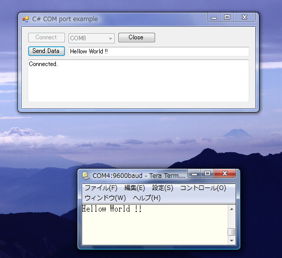
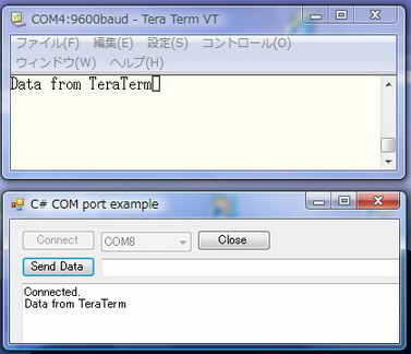
下記の上側のウィンドウは MCHPFSUSB Framework 2.3 付属ソフトのウィンドウです。 下側は 通信ソフトTeraTermのウィンドウです。
画面は 付属ソフトからUSB経由で Hellow World !! を送信した結果、PIC側からRS232C経由でエコーバックがありこれをTeraTermに表示
したものです。
| PIC18F4550-PC 間 CDCクラス通信 ( 自作PICキバン + Microchip社デモソフト) |
動作結果 |
デモソフト: Serial Emulator 送信側:PICDEMサンプルソフト 受信側:Tera Term ①左記ウィンドウのテキストボックスに文字列 Hellow World !!をキーインして、Send Dataボタンをクリックする ②PIC側キバン(PICDEM相当自作キバン)では、USBケーブル経由送信されてきたたこの文字列を受信した後、この文字列をRS232Cケーブル経由でRS232C通信でエコーバックする ③PC側ではエコーバックされてきたデータを通信ソフトTera Termで受信し、これをウィンドウに表示する。 ★PC側のソフト → PC .NET C# (注)ウィンドウの背景にある画像は、本テーマとは関係ありません |
 |
デモソフト: Serial Emulator 送信側:Tera Term 受信側:PICDEMサンプルソフト ①Tera Term(注)に Data from TeraTerm とキーイン後、エンターキーを押しRS232C経由でPIC側(PICDEM相当)にデータを送信する。 ②PIC側では受信データをそのままUSBケーブル経由でPC側に送信する。 ③PC側ではPICDEMデモソフトの右記ウィンドウのリッチテキストボックスで受信データを表示する。 ★PC側のソフト → PC .NET C# (注)TeraTermのローカルエコーがONであるのでキーインしたデータが表示されている。 |
 |
■ USB PIC18F4550-PC間 CDCクラス通信(液晶付)
PIC18F4550に液晶を接続した USB通信 送受信の例を紹介します。 →PC側ソフト(VC#)
→PC側ソフト(VC++)
本ソフトは USBフレームワークMCHPFSUSB Framework 2.3のPICDEMデモボード用サンプルソフトに追加、変更を加えたものです。不足情報は
このソフトを参照願います
<試作品仕様>
・PC側からデータをPIC側にUSB CDCクラス通信で送信する。
・PIC側では受信した文字列を液晶上段に、受信データに基づき返信したデータを液晶下段に表示する。
・PC側でも受信したデータをテキストボックスに表示する。
・PC側からの送信データ 及びPIC側からの返信データは以下とする。
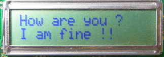
① How are you ? → I am fine !!
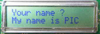
② Your name ? → My name is PIC
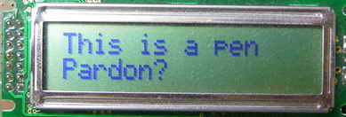
③ This is a pen → Pardon?
<試作品回路図> (→回路図のPDFファイル)
PIC18F4550をつかった場合の回路図を以下に示します。

<試作品外観>下記の写真には上記回路図にはない、また本テーマと関係のない部品が多々写っています
<プログラム例>
以下のプログラムはマイクロチップ社のMCHPFSUSB Framework 2.3をダウンロードして解凍後PCにできる…\Microchip Solutions\ USB Device - CDC - Basic Demo\CDC
- Basic Demo - Firmwareフォルダに収納されているプロジェクトファイル USB Device - CDC - Serial
Emulator - C18 - PICDEM FSUSB.mcpに含まれているファイルをもとに作成しています。 プログラム生成に際し 関係するファイルは下記のに示すようにたくさんあります。 以下の内容記載ファイルは、
ユーザープログラムを作成する際に 変更する必要がある4つのファイルですが、本ソフトにおいては②のusb_config.h と ③のusb_descriptor.cはサンプルソフトに対しコメントの翻訳、追加、削除等は行ないましたがソースコードの変更はおこなっていません。ソースコードの変更をおこなったのは①のmain.c と④のHardwareProfile.hの2つのファイルです。
① main.c (★)
② usb_config.h
③ usb_descriptors.c
④ HardwareProfile.h (★)
(注) (★):ソースコードを変更したファイル
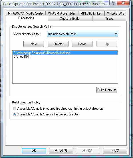
インクルード :
① [Project][Build Option][Project] で開く下記ダイアログのShow directories for Include
Search Path に
…Microchip Solutions\Microchip\Include と …\mcc18\h を設定します。
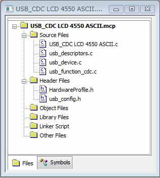
② プロジェクトファイルの中のプロジェクトウィドウに下記を追加します。
usb_device.c と usb_function_cdc.cのファイルは直接このプロジェクトウィンドウに追加する。(上記のInclude
Serch Pathに usb_device.c と usb_function_cdc.cのファイルがあるパスを追加しても何故かコンパイルできませんでした)
<プログラム例>
//液晶付 USB #include <p18f4550.h> #include <stdio.h> #include <delays.h> #include <stdio.h> #include <stdlib.h> #include <string.h> #include "GenericTypeDefs.h" #include "Compiler.h" #include "./USB/usb_device.h" #include "./USB/usb.h" #include "./USB/usb_function_cdc.h" #include "usb_config.h" #include "HardwareProfile.h" #include "1lcd_lib_C18.h" #include "1lcd_lib_C18.c" #define USE_SELF_POWER_SENSE_IO //ボード電源検出制御有り #define USE_USB_BUS_SENSE_IO //USBバス電源検出制御有り // ★ [Project] [Project Options...] [Project] Include Serch Path に下記directoryを追加のする // .\Microchip Solutions\Microchip\Include // ★ MPLAB Project Window のSource Files に 下記の3つのソースファイルを追加する // 1. usb_device.c、 // 2. usb_function_cdc.c、 // 3. usb_descriptors.c // ★ MPLAB Project Window のHeader Files に 下記の2つのヘッダーファイルを追加する // 1. HardwareProfiles.h // 2. usb_config.h //LED点滅制御関係 #define mInitAllLEDs() LATD &= 0xF0; TRISD &= 0xF0; #define mLED_1 LATDbits.LATD0 #define mLED_2 LATDbits.LATD1 #define mLED_3 LATDbits.LATD2 #define mLED_4 LATDbits.LATD3 #define mGetLED_1() mLED_1 #define mGetLED_2() mLED_2 #define mGetLED_3() mLED_3 #define mGetLED_4() mLED_4 #define mLED_1_On() mLED_1 = 1; #define mLED_2_On() mLED_2 = 1; #define mLED_3_On() mLED_3 = 1; #define mLED_4_On() mLED_4 = 1; #define mLED_1_Off() mLED_1 = 0; #define mLED_2_Off() mLED_2 = 0; #define mLED_3_Off() mLED_3 = 0; #define mLED_4_Off() mLED_4 = 0; #define mLED_1_Toggle() mLED_1 = !mLED_1; #define mLED_2_Toggle() mLED_2 = !mLED_2; #define mLED_3_Toggle() mLED_3 = !mLED_3; #define mLED_4_Toggle() mLED_4 = !mLED_4; #pragma config PLLDIV = 5 // (20 MHz crystal on PICDEM FS USB board) #pragma config CPUDIV = OSC1_PLL2 //システムクロック:20MHz (= 20MHz ÷ 1) #pragma config USBDIV = 2 // Clock source from 96MHz PLL/2 #pragma config FOSC = HSPLL_HS //Oscillator Selection bits: #pragma config FCMEN = OFF //Fail-Safe Clock Monitor Enable bit: #pragma config IESO = OFF //Internal/External Oscillator Switchover bit: #pragma config PWRT = ON //パワーアップタイマ有効 Power-up Timer Enable bit: #pragma config BOR = ON //低電圧リセット有効 Brown-out Reset Enable bits: #pragma config BORV = 3 //最小電圧にセットBrown-out Voltage bits: #pragma config VREGEN = ON //USB Voltage Regulator Enable bit: #pragma config WDT = OFF //Watchdog Timer Enable bit: #pragma config WDTPS = 32768 //1:32768 Watchdog Timer Postscale Select bits: #pragma config MCLRE = ON //MCLR Pin Enable bit: #pragma config LPT1OSC = OFF //タイマ1低電圧動作:OFF Low-Power Timer 1 Oscillator Enable bit: #pragma config PBADEN = OFF //ポートB アナログAD入力モード:OFF PORTB A/D Enable bit: //#pragma config CCP2MX = ON //CCP2 MUX bit: #pragma config STVREN = ON //Stack Full/Underflow Reset Enable bit: #pragma config LVP = OFF //Single-Supply ICSP Enable bit: //#pragma config ICPRT = OFF // Dedicated In-Circuit Debug/Programming Port (ICPORT) Enable bit: #pragma config XINST = OFF // Extended Instruction Set Enable bit: #pragma config CP0 = OFF //Background Debugger Enable bit: #pragma config CP1 = OFF //Code Protection bit Block 1: //#pragma config CP2 = OFF //Code Protection bit Block 2: //#pragma config CP3 = OFF //Code Protection bit Block 3: #pragma config CPB = OFF //Boot Block Code Protection bit: //#pragma config CPD = OFF //Data EEPROM Code Protection bit: #pragma config WRT0 = OFF //Write Protection bit Block 0: #pragma config WRT1 = OFF //Write Protection bit Block 1: //#pragma config WRT2 = OFF //Write Protection bit Block 2: //#pragma config WRT3 = OFF //Write Protection bit Block 3: #pragma config WRTB = OFF //Boot Block Write Protection bit: #pragma config WRTC = OFF //Configuration Register Write Protection bit: //#pragma config WRTD = OFF //Data EEPROM Write Protection bit: #pragma config EBTR0 = OFF //Table Read Protection bit Block 0: #pragma config EBTR1 = OFF //Table Read Protection bit Block 1: //#pragma config EBTR2 = OFF //Table Read Protection bit Block 2: //#pragma config EBTR3 = OFF //Table Read Protection bit Block 3: #pragma config EBTRB = OFF //Boot Block Table Read Protection: char USB_Out_Buffer[CDC_DATA_OUT_EP_SIZE]; // char ReceiveData[CDC_DATA_IN_EP_SIZE]; unsigned char DataDetect = 0; // Number of characters in the buffer char tempBuf[20]; char tempBuf1[20]; char tempBuf2[20]; char* str; int SendDataBox = 0; void lcd_printf(char* strx) //液晶表示補助関数 { while(*strx) //文字列終端の '\0'を検出するまで { lcd_data(*strx); // 1文字表示 strx++; } } void BlinkUSBStatus(void) //LED点灯制御 { static WORD led_count=0; if(led_count == 0)led_count = 10000U; led_count--; #define mLED_Both_Off() {mLED_1_Off();mLED_2_Off();} #define mLED_Both_On() {mLED_1_On();mLED_2_On();} #define mLED_Only_1_On() {mLED_1_On();mLED_2_Off();} #define mLED_Only_2_On() {mLED_1_Off();mLED_2_On();} if(USBSuspendControl == 1) { if(led_count==0) { mLED_1_Toggle(); if(mGetLED_1()) { mLED_2_On(); } else { mLED_2_Off(); } }//end if } else { if(USBDeviceState == DETACHED_STATE) { mLED_Both_Off(); } else if(USBDeviceState == ATTACHED_STATE) { mLED_Both_On(); } else if(USBDeviceState == POWERED_STATE) { mLED_Only_1_On(); } else if(USBDeviceState == DEFAULT_STATE) { mLED_Only_2_On(); } else if(USBDeviceState == ADDRESS_STATE) { if(led_count == 0) { mLED_1_Toggle(); mLED_2_Off(); }//end if } else if(USBDeviceState == CONFIGURED_STATE) { if(led_count==0) { mLED_1_Toggle(); if(mGetLED_1()) { mLED_2_Off(); } else { mLED_2_On(); } }//end if }//end if(...) }//end if(UCONbits.SUSPND...) } void ProcessIO(void) { char strTemp[20]; char How[] = "How are you ? "; char Fine[] = "I am fine !! \n"; // 液晶表示で既表示を消去するために16文字固定送信 char YourName[] = "Your name ? "; char MyName[] = "My name is PIC \n"; // 液晶表示で既表示を消去するために16文字固定送信 char Pardon[] = "Pardon? \n"; // 液晶表示で既表示を消去するために16文字固定送信 int i; BlinkUSBStatus(); //LED点灯制御 if((USBDeviceState < CONFIGURED_STATE)||(USBSuspendControl==1)) return;//サスペンド状態等であれば関数終了 //USB通信によるデータ受信 DataDetect // USB受信バッファーデータ有無検出 戻り値 : 実際に取得したバイト数 = getsUSBUSART(ReceiveData,64); //ポインタ RS232_Out_Data に64バイトの文字取得を実行 if(DataDetect != 0) //受信データ有りの場合 { i = 0; for(i = 0; i < 64; i++) { if(ReceiveData[i] == '\r') break; } ReceiveData[i] = '\0'; //文字列化 if(strcmp(ReceiveData,How) == 0) { str = Fine; lcd_cmd(0x80); //1行目へ sprintf(&tempBuf1,"%s ",ReceiveData); lcd_printf(&tempBuf1[0]); //受信データを液晶に表示 lcd_cmd(0xC0); //2行目 lcd_printf(str); //送信データを液晶に表示 } else if(strcmp(ReceiveData,YourName) == 0) { str = MyName; lcd_cmd(0x80); //1行目へ sprintf(&tempBuf1,"%s ",ReceiveData); lcd_printf(&tempBuf1[0]); //受信データを液晶に表示 lcd_cmd(0xC0); //2行目 lcd_printf(str); //送信データを液晶に表示 } else { str = Pardon; lcd_cmd(0x80); //1行目へ sprintf(&tempBuf,"%s ",ReceiveData); lcd_printf(&tempBuf[0]); //受信データを液晶に表示 lcd_cmd(0xC0); //2行目 lcd_printf(str); //送信データを液晶に表示 } SendDataBox = 1; //送信データ有 } //USB通信によるデータ送信 if((USBUSARTIsTxTrfReady()) && (SendDataBox == 1)) //USB送信準備完了で、かつ 送信データがあるなら { SendDataBox = 0; //送信データ無し putUSBUSART(str,strlen(str)); //USB通信でデータ列strのデータを、strlen(str)個送る。 一括USB送信 } } #if defined(USB_CDC_SET_LINE_CODING_HANDLER) void mySetLineCodingHandler(void) //通信条件設定 { //If the request is not in a valid range if(cdc_notice.GetLineCoding.dwDTERate.Val > 115200) //115200bps以上のボーレートが設定された場合 { } else { DWORD_VAL dwBaud; CDCSetBaudRate(cdc_notice.GetLineCoding.dwDTERate.Val);//CDCドライバーに於ける、ボーレート設定 dwBaud.Val = (GetSystemClock()/4)/line_coding.dwDTERate.Val-1; //UART設定 SPBRG = dwBaud.v[0]; SPBRGH = dwBaud.v[1]; } } #endif // ****************************************************************************************************** // ************** USB Callback Functions **************************************************************** // ****************************************************************************************************** void USBCBSuspend(void) //サスペンド状態になるとこの関数が呼び出される { } //--------------------------------------------------------------------------- void USBCBWakeFromSuspend(void) // サスペンド状態からウェークアップする時この関数は呼び出される { } //-------------------------------------------------------------------- void USBCB_SOF_Handler(void) // 1msec毎に、SOFパケット送信時この関数は呼び出される呼び出される。 { // No need to clear UIRbits.SOFIF to 0 here. // Callback caller is already doing that. } //-------------------------------------------------------- void USBCBErrorHandler(void) //開発段階でのデバック エラー検出 { } //------------------------------------------------------------------ void USBCBCheckOtherReq(void)//ホスト(PC)からのSSETUP要求が来た場合によびだされる。 { USBCheckCDCRequest(); } //------------------------------------------------------------------- void USBCBStdSetDscHandler(void)//SET_DESCRIPTOR要求がきた場合にこの関数は呼び出される。 { //ほとんどのアプリケーションでは使われることはない } //--------------------------------------------------------------------- void USBCBInitEP(void)//ホスト(PC)からSET_CONFIGURATION 要求がきた場合にこの関数はよびだされる。 { //デバイスの現状に合わせ初期化される。 CDCInitEP(); } //--------------------------------------------------------------- void USBCBSendResume(void)// ホスト(PC)ウェイク待ち時間設定 { static WORD delay_count; USBResumeControl = 1; // Start RESUME signaling delay_count = 1800U; // Set RESUME line for 1-13 ms do { delay_count--; }while(delay_count); USBResumeControl = 0; } //----------------------------------------------------------- void USBCBEP0DataReceived(void)//この関数は、エンドポイント0のデータを受信した場合に呼び出される。 { } //---------------------------------------------------------------------- void main(void) { unsigned char i; USBDeviceInit(); //usb_device.c. Initializes USB module SFRs and firmware //variables to known states. for (i=0; i<sizeof(USB_Out_Buffer); i++) //USB バッファー初期化 { USB_Out_Buffer[i] = 0; } mInitAllLEDs(); //LED初期化 TRISBbits.TRISB0=0; //液晶コントロール端子RB0出力モード TRISBbits.TRISB2=0; //同上RB2出力モード TRISAbits.TRISA1 = 1; //バス電圧検出ポートRA1を入力ポートに設定 TRISAbits.TRISA2 = 1; //ボード電源電圧検出ポートRA2を入力ポートに設定 lcd_init(); // LCD初期化 lcd_cmd(0b00001100); // カーソル:OFF ブリンク:OFF lcd_clear(); sprintf(tempBuf,"USB6"); //文字列としてバッファーに収納 lcd_printf(tempBuf); lcd_cmd(0xC0);//2行目の先頭へ sprintf(tempBuf, " Start !!"); //文字列としてバッファーに収納 lcd_printf(tempBuf); while(1) { USBDeviceTasks(); //USB関連タスクチェック CDCTxService(); //デバイスのコンフィグレーション確定 ProcessIO(); //ユーザプログラム } } //*************************************************************************************************** //*************************************************************************************************** //*************************************************************************************************** // usb_config.h ファイル //USB通信条件設定 #ifndef USBCFG_H #define USBCFG_H /** DEFINITIONS ****************************************************/ #define USB_EP0_BUFF_SIZE 8 // エンドポイント0のバッファーサイズを設定 8, 16, 32, or 64 bytes. // Using larger options take more SRAM, but // does not provide much advantage in most types // of applications. Exceptions to this, are applications // that use EP0 IN or OUT for sending large amounts of // application related data. #define USB_MAX_NUM_INT 1 // 内蔵するインターフェースの最大数 For tracking Alternate Setting //Device descriptor - if these two definitions are not defined then // a ROM USB_DEVICE_DESCRIPTOR variable by the exact name of device_dsc // must exist. #define USB_USER_DEVICE_DESCRIPTOR &device_dsc #define USB_USER_DEVICE_DESCRIPTOR_INCLUDE extern ROM USB_DEVICE_DESCRIPTOR device_dsc //Configuration descriptors - if these two definitions do not exist then // a ROM BYTE *ROM variable named exactly USB_CD_Ptr[] must exist. #define USB_USER_CONFIG_DESCRIPTOR USB_CD_Ptr #define USB_USER_CONFIG_DESCRIPTOR_INCLUDE extern ROM BYTE *ROM USB_CD_Ptr[] //Make sure only one of the below "#define USB_PING_PONG_MODE" //ピンポンバッファーの使用モード設定 //is uncommented. //#define USB_PING_PONG_MODE USB_PING_PONG__NO_PING_PONG #define USB_PING_PONG_MODE USB_PING_PONG__FULL_PING_PONG //#define USB_PING_PONG_MODE USB_PING_PONG__EP0_OUT_ONLY //#define USB_PING_PONG_MODE USB_PING_PONG__ALL_BUT_EP0 //NOTE: This mode is not supported in PIC18F4550 family rev A3 devices #define USB_POLLING /* Parameter definitions are defined in usb_device.h */ //パラメータの定義 #define USB_PULLUP_OPTION USB_PULLUP_ENABLE //プルアップ // USB_PULLUP_DISABLE #define USB_TRANSCEIVER_OPTION USB_INTERNAL_TRANSCEIVER //USBトランシーバ 有無の設定 // USB_EXTERNAL_TRANSCEIVER #define USB_SPEED_OPTION USB_FULL_SPEED //フルスピード or ロースピード の設定 // USB_LOW_SPEED (not valid option for PIC24F devices) #define USB_NUM_STRING_DESCRIPTORS 3 /** DEVICE CLASS USAGE *********************************************/ #define USB_SUPPORT_DEVICE #define USB_USE_CDC /** ENDPOINTS ALLOCATION *******************************************/ #define USB_MAX_EP_NUMBER 3 //最大エンドポイント番号 /* CDC */ #define CDC_COMM_INTF_ID 0x0 //CDC共通用インターフェース番号 : 0 #define CDC_COMM_EP 2 //CDC共通用エンドポイント番号 : 2 #define CDC_COMM_IN_EP_SIZE 8 //CDC共通用エンドポイントのサイズ : 8バイト #define CDC_DATA_INTF_ID 0x01 //CDCデータ用インターフェース番号 : 1 #define CDC_DATA_EP 3 //CDCデータ用エンドポイント番号 : 3 #define CDC_DATA_OUT_EP_SIZE 64 //CDCデータ用出力エンドポイントのサイズ : 64バイト #define CDC_DATA_IN_EP_SIZE 64 //CDCデータ用入力エンドポイントのサイズ : 64バイト #define USB_CDC_SET_LINE_CODING_HANDLER mySetLineCodingHandler //#define USB_CDC_SUPPORT_HARDWARE_FLOW_CONTROL //#define USB_CDC_SUPPORT_ABSTRACT_CONTROL_MANAGEMENT_CAPABILITIES_D2 //Send_Break command #define USB_CDC_SUPPORT_ABSTRACT_CONTROL_MANAGEMENT_CAPABILITIES_D1 //Set_Line_Coding, Set_Control_Line_State, Get_Line_Coding, and Serial_State commands /** DEFINITIONS ****************************************************/ #endif //USBCFG_H //*************************************************************************************************************** //*************************************************************************************************************** //*************************************************************************************************************** //-- usb_descriptors.c //----デスクリプタの設定---------- #ifndef __USB_DESCRIPTORS_C #define __USB_DESCRIPTORS_C /** INCLUDES *******************************************************/ #include "GenericTypeDefs.h" #include "Compiler.h" #include "usb_config.h" #include "./USB/usb.h" #include "./USB/usb_function_cdc.h" /** CONSTANTS ******************************************************/ #if defined(__18CXX) #pragma romdata #endif /* デバイス デスクリプタ Device Descriptor */ ROM USB_DEVICE_DESCRIPTOR device_dsc= { 0x12, //デスクリプタのサイズ(固定) 0x12:18バイト Size of this descriptor in bytes USB_DESCRIPTOR_DEVICE, // DEVICE descriptor type 0x0200, // USB Spec Release Number in BCD format CDC_DEVICE, // Class Code 0x00, // Subclass code 0x00, // Protocol code USB_EP0_BUFF_SIZE, // Max packet size for EP0, see usb_config.h 0x4D8, // ★ ベンダーID Vendor ID 0x000A, // ★ プロダクトID Product ID: CDC RS-232 Emulation Demo 0x0001, // Device release number in BCD format 0x01, // Manufacturer string index 0x02, // Product string index 0x00, // Device serial number string index 0x01 // Number of possible configurations }; /* コンフィグレーション デスクリプタ Configuration 1 Descriptor */ ROM BYTE configDescriptor1[]={ /* コンフィグレーション デスクリプタ Configuration Descriptor */ 0x09,//sizeof(USB_CFG_DSC), // デスクリプタのサイズ Size of this descriptor in bytes USB_DESCRIPTOR_CONFIGURATION, // CONFIGURATION descriptor type 67,0, // Total length of data for this cfg 2, // Number of interfaces in this cfg 1, // Index value of this configuration 0, // Configuration string index _DEFAULT | _SELF, // Attributes, see usb_device.h 50, // Max power consumption (2X mA) /* インターフェースデスクリプタ(共通用) Interface Descriptor */ 9,//sizeof(USB_INTF_DSC), // デスクリプタのサイズ Size of this descriptor in bytes USB_DESCRIPTOR_INTERFACE, // INTERFACE descriptor type 0, // インターフェース番号 : 0 Interface Number 0, // Alternate Setting Number 1, // Number of endpoints in this intf COMM_INTF, // Class code ABSTRACT_CONTROL_MODEL, // Subclass code V25TER, // Protocol code 0, // Interface string index /* CDCクラス仕様 デスクリプタ CDC Class-Specific Descriptors */ sizeof(USB_CDC_HEADER_FN_DSC), CS_INTERFACE, DSC_FN_HEADER, 0x10,0x01, sizeof(USB_CDC_ACM_FN_DSC), CS_INTERFACE, DSC_FN_ACM, USB_CDC_ACM_FN_DSC_VAL, sizeof(USB_CDC_UNION_FN_DSC), CS_INTERFACE, DSC_FN_UNION, CDC_COMM_INTF_ID, CDC_DATA_INTF_ID, sizeof(USB_CDC_CALL_MGT_FN_DSC), CS_INTERFACE, DSC_FN_CALL_MGT, 0x00, CDC_DATA_INTF_ID, /* エンドポイント デスクリプタ Endpoint Descriptor */ //sizeof(USB_EP_DSC),DSC_EP,_EP02_IN,_INT,CDC_INT_EP_SIZE,0x02, 0x07,/*sizeof(USB_EP_DSC)*/ USB_DESCRIPTOR_ENDPOINT, //Endpoint Descriptor _EP02_IN, //入力用エンドポイントアドレス EndpointAddress _INTERRUPT, //インタラプト転送 Attributes 0x08,0x00, //エンドポイントのサイズ : 8バイト size 0x02, //ホストからのポーリング周期 : 2msec Interval /* インターフェースデスクリプタ(データ用) Interface Descriptor */ 9,//sizeof(USB_INTF_DSC), // Size of this descriptor in bytes USB_DESCRIPTOR_INTERFACE, // INTERFACE descriptor type 1, // インターフェース番号 : 1 Interface Number 0, // Alternate Setting Number 2, // Number of endpoints in this intf DATA_INTF, // Class code 0, // Subclass code NO_PROTOCOL, // Protocol code 0, // Interface string index /* エンドポイント デスクリプタ Endpoint Descriptor */ //sizeof(USB_EP_DSC),DSC_EP,_EP03_OUT,_BULK,CDC_BULK_OUT_EP_SIZE,0x00, 0x07,/*sizeof(USB_EP_DSC)*/ USB_DESCRIPTOR_ENDPOINT, //Endpoint Descriptor _EP03_OUT, //出力用エンドポイントアドレス EndpointAddress _BULK, //バルク転送 Attributes 0x40,0x00, //エンドポイントのサイズ : 64バイト size 0x00, //Interval /* エンドポイント デスクリプタ Endpoint Descriptor */ //sizeof(USB_EP_DSC),DSC_EP,_EP03_IN,_BULK,CDC_BULK_IN_EP_SIZE,0x00 0x07,/*sizeof(USB_EP_DSC)*/ USB_DESCRIPTOR_ENDPOINT, //Endpoint Descriptor _EP03_IN, //入力用エンドポイントアドレス EndpointAddress _BULK, //バルク転送 Attributes 0x40,0x00, //エンドポイントのサイズ: 64バイト size 0x00, //Interval }; // ストリングデスクリプタ Language code string descriptor ROM struct{BYTE bLength;BYTE bDscType;WORD string[1];}sd000={ sizeof(sd000),USB_DESCRIPTOR_STRING,{0x0409}}; //製造者に係る記事 デスクリプタ Manufacturer string descriptor ROM struct{BYTE bLength;BYTE bDscType;WORD string[25];}sd001={ sizeof(sd001),USB_DESCRIPTOR_STRING, {'M','i','c','r','o','c','h','i','p',' ', 'T','e','c','h','n','o','l','o','g','y',' ','I','n','c','.' }}; //製品に係る記事 Product string descriptor ROM struct{BYTE bLength;BYTE bDscType;WORD string[25];}sd002={ sizeof(sd002),USB_DESCRIPTOR_STRING, {'C','D','C',' ','R','S','-','2','3','2',' ', 'E','m','u','l','a','t','i','o','n',' ','D','e','m','o'} }; //Array of configuration descriptors ROM BYTE *ROM USB_CD_Ptr[]= { (ROM BYTE *ROM)&configDescriptor1 }; //Array of string descriptors ROM BYTE *ROM USB_SD_Ptr[]= { (ROM BYTE *ROM)&sd000, (ROM BYTE *ROM)&sd001, (ROM BYTE *ROM)&sd002 }; #pragma code #endif /** EOF usb_descriptors.c ****************************************************/ //********************************************************************************************************** //********************************************************************************************************** //********************************************************************************************************** //--------------------HardwareProfile.h #define CLOCK_FREQ 48000000 #define GetSystemClock() (CLOCK_FREQ) //バス電源検出 (以下の部分はUSB_BUS_SENSEを別のファイルで使用しているの必要) #if defined(USE_USB_BUS_SENSE_IO) //バス電圧検出制御有りの場合 #define USB_BUS_SENSE PORTAbits.RA1 //RA1をバス電源検出ポートに設定 #else #define USB_BUS_SENSE 1 #endif //ボード電源検出 (以下の部分はUSB_BUS_SENSEを別のファイルで使用しているの必要) #if defined(USE_SELF_POWER_SENSE_IO) //ボード電圧検出制御有りの場合 #define self_power PORTAbits.RA2 //RA2をボード電源検出ポートに設定 #else #define self_power 1 #endif //***************************************************************************************************** //***************************************************************************************************** //***************************************************************************************************** //************************************************ //インクルードファイル 1lcd_lib_C18.h //このファイルは後閑哲也さんが設計されたCCSコンパイラ用液晶表示ライブラリを //C18コンパイラ用に変更したものです。 //************************************************ #define lcd_port LATD //DataOutPort pin : 上位4bit //#define lcd_stb LATDbits.LATD0 //stb OutPort #define lcd_stb LATBbits.LATB0 //stb OutPort //#define lcd_rs LATDbits.LATD2 // rs OutPort #define lcd_rs LATBbits.LATB2 // rs OutPort #define port_Mode TRISD // Port Mode set void lcd_data(char asci); void lcd_cmd(char cmd); void lcd_clear(void); void lcd_init(void); void lcd_out(char code, char flag); //********************************************************************************************************* //********************************************************************************************************* //********************************************************************************************************* //*********************************************** //インクルードファイル 1lcd_lib_C18.c //このファイルは後閑哲也さんが設計されたCCSコンパイラ用液晶表示ライブラリを //C18コンパイラ用に変更したものです。 //*********************************************** /////////////////////////////////////////////// // 液晶表示器制御ライブラリ for C18コンパイラー // 内蔵関数は以下 // lcd_init() ----- 初期化 // lcd_cmd(cmd) ----- コマンド出力 // lcd_data(chr) ----- 1文字表示出力 // lcd_clear() ----- 全消去 ////////////////////////////////////////////// #include "delays.h" #include "1lcd_lib_C18.h" //////// データ出力サブ関数 void lcd_out(char code, char flag) { port_Mode = 0; // PIC側の DataPort、stbPort、 rsPort を出力モードに設定 lcd_port = code & 0xF0; if (flag == 0) lcd_rs = 1; //表示データの場合 else lcd_rs = 0; //コマンドデータの場合 Delay10TCYx(1); //10NOP lcd_stb = 1; //strobe out Delay10TCYx(1); //10NOP lcd_stb = 0; //reset strobe } //////// 1文字表示関数 void lcd_data(char asci) { lcd_out(asci, 0); //上位4ビット出力 lcd_out(asci<<4, 0); //下位4ビット出力 Delay10TCYx(50); //500NOP (50μsec待ち at 40MHz) } /////// コマンド出力関数 void lcd_cmd(char cmd) { lcd_out(cmd, 1); //上位4ビット出力 lcd_out(cmd<<4, 1); //下位4ビット出力 if((cmd & 0x03) != 0) Delay10KTCYx(2); //2msec待ち at 40MHz else Delay10TCYx(50); //50usec待ち at 40MHz } /////// 全消去関数 void lcd_clear(void) { lcd_cmd(0x01); //初期化コマンド出力 // Delay10KTCYx(15); //15msec待ち at 40MHz } /////// 初期化関数 void lcd_init(void) { lcd_out(0x30, 1); //8bit mode set Delay10KTCYx(5); //5msec待ち at 40MHz lcd_out(0x30, 1); //8bit mode set Delay10KTCYx(1); //1msec待ち at 40MHz lcd_out(0x30, 1); //8bit mode set Delay10KTCYx(1); //1msec待ち at 40MHz lcd_out(0x20, 1); //4bit mode set Delay10KTCYx(1); //1msec待ち at 40MHz lcd_cmd(0x2E); //DL=0 4bit mode lcd_cmd(0x08); //display off C=D=B=0 lcd_cmd(0x0D); //display on C=D=1 B=0 lcd_cmd(0x06); //entry I/D=1 S=0 lcd_cmd(0x01); //all clear }
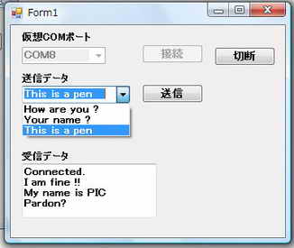
<動作結果>
① PC側のウィンドウから仮想COM8ポートを選択してを接続ボタンをクリックする。
② USB接続が完了して受信データテキストボックスに Connected が表示される。
③ 送信データ用コンボボックススから How are you ? を選択して送信ボタンをクリックする。
④ PIC側で受信した受信データ How are you ? が液晶の上段に表示されています。
⑤ 返信データとして I am fine !! がプログラムで選択され、これを液晶下段に表示されています。また、同時にPC側にも送信されています。
⑥ この結果、PC側では 受信したデータ I am fine !! を受信データ用テキストボックスに表示しています。
⑦ 同様に Your name ? を送信した場合 My name is PIC が返信された場合も表示されています。
⑧ 同様に This is a pen を送信した場合 Pardon? が返信された場合も表示されています。
| PC側 送受信ウィンドウ |
PIC側 液晶画面 | |
 |
 |
|
 |
||
 |
■ PIC18F4550-PC 間 汎用クラス通信(ポーリング方式)
( 自作キバン + Microchip社デモソフト (その1))
マイクロチップDemoBoard(PICDEM FS USB DM163025)($59.99ドル)相当の自作キバンによるUSB通信を行なったので紹介します。
USBフレームワークMCHPFSUSB Framework 2.3にはPICDEMでそのまま動作するPIC側ソフトとPC側ソフトがサンプルソフトとして公開されて
います。汎用クラスの場合PC側のソフトはVC++ と BCBだけとなっています。(VBとC#のサンプルありません。やはり低級な世界はポインタが
必須なのでしょう) PICDEMに対しての変更は下記のみで付属のUSBフレームワークMCHPFSUSB Framework 2.3付属のCDCクラスサンプル
ソフトがそのまま動くようにしました.。 →PC側ソフト
① PIC : PIC18F4550(TQFP) → PIC18F4550(PDIP)
② USBバス電源、ボード電源切り替え回路簡略化
<試作品の仕様>
・PIC側の可変抵抗器の値をPC側に側に ポーリングによるUSB 汎用(Generic)クラス通信で送信する。
・デバイスドライバはWDMドライバを用いる
・PIC側からの送信データは8msec毎にPC側におくり、PC側では送られてきたデータをステータスバーに表示する。
・送受信中USBコネクタを抜き差ししてもPnP(Plug and Play)によりアタッチの自動検出を支障なく実施してステータスバー表示がすみやかに
できること。
<試作品回路図>(→回路図のPDFファイル)
PIC18F4550をつかった場合の回路図を以下に示します。
<試作品外観>下記の写真には上記回路図にはない、また本テーマと関係のない部品が多々写っています
<プログラム例>
 以下は、マイクロチップデモキバンPICDEMFSUSBのサンプルソフトに若干のコメントを翻訳、追加したmain()とuser()です。ソース
コードの変更は行なっていません。

//USB Generic Demo   main()
#include "Compiler.h"
#include "HardwareProfile.h"
#include "GenericTypeDefs.h"
#include "USB/usb_device.h"
#include "USB/usb.h"
#include "USB/usb_function_generic.h"
#include "usb_config.h"
#include "user.h"                              // Modifiable

//#if defined(PICDEM_FS_USB)      // Configuration bits for PICDEM FS USB Demo Board (based on PIC18F4550)
#pragma config PLLDIV   = 5         // (20 MHz crystal on PICDEM FS USB board)
#pragma config CPUDIV   = OSC1_PLL2     //システムクロック:20MHz (= 20MHz ÷ 1)
#pragma config USBDIV   = 2         // Clock source from 96MHz PLL/2
#pragma config FOSC     = HSPLL_HS      //Oscillator Selection bits:
#pragma config FCMEN    = OFF   //Fail-Safe Clock Monitor Enable bit:
#pragma config IESO     = OFF   //Internal/External Oscillator Switchover bit:
#pragma config PWRT     = ON    //パワーアップタイマ有効  Power-up Timer Enable bit:
#pragma config BOR      = ON    //低電圧リセット有効 Brown-out Reset Enable bits:
#pragma config BORV     = 3             //最小電圧にセットBrown-out Voltage bits:
#pragma config VREGEN   = ON    //USB Voltage Regulator Enable bit:
#pragma config WDT      = OFF   //Watchdog Timer Enable bit:
#pragma config WDTPS    = 32768 //1:32768  Watchdog Timer Postscale Select bits:
#pragma config MCLRE    = ON    //MCLR Pin Enable bit:
#pragma config LPT1OSC  = OFF   //タイマ1低電圧動作:OFF Low-Power Timer 1 Oscillator Enable bit:
#pragma config PBADEN   = OFF   //ポートB アナログAD入力モード:OFF  PORTB A/D Enable bit:
//#pragma config CCP2MX   = ON  //CCP2 MUX bit:
#pragma config STVREN   = ON    //Stack Full/Underflow Reset Enable bit:
#pragma config LVP      = OFF   //Single-Supply ICSP Enable bit:
//#pragma config ICPRT    = OFF // Dedicated In-Circuit Debug/Programming Port (ICPORT) Enable bit:
#pragma config XINST    = OFF   // Extended Instruction Set Enable bit:
#pragma config CP0      = OFF   //Background Debugger Enable bit:
#pragma config CP1      = OFF   //Code Protection bit Block 1:
//#pragma config CP2    = OFF   //Code Protection bit Block 2:
//#pragma config CP3    = OFF   //Code Protection bit Block 3:
#pragma config CPB      = OFF   //Boot Block Code Protection bit:
//#pragma config CPD    = OFF   //Data EEPROM Code Protection bit:
#pragma config WRT0     = OFF   //Write Protection bit Block 0:
#pragma config WRT1     = OFF   //Write Protection bit Block 1:
//#pragma config WRT2   = OFF   //Write Protection bit Block 2:
//#pragma config WRT3   = OFF   //Write Protection bit Block 3:
#pragma config WRTB     = OFF   //Boot Block Write Protection bit:
#pragma config WRTC     = OFF   //Configuration Register Write Protection bit:
//#pragma config WRTD   = OFF   //Data EEPROM Write Protection bit:
#pragma config EBTR0    = OFF   //Table Read Protection bit Block 0:
#pragma config EBTR1    = OFF   //Table Read Protection bit Block 1:
//#pragma config EBTR2  = OFF   //Table Read Protection bit Block 2:
//#pragma config EBTR3  = OFF   //Table Read Protection bit Block 3:
#pragma config EBTRB    = OFF   //Boot Block Table Read Protection:


/** VARIABLES ******************************************************/
#pragma udata
extern USB_HANDLE USBGenericOutHandle;
extern USB_HANDLE USBGenericInHandle;
extern DATA_PACKET INPacket;
extern DATA_PACKET OUTPacket;

static void InitializeSystem(void);
void USBDeviceTasks(void);
void YourHighPriorityISRCode(void);
void YourLowPriorityISRCode(void);


#pragma code


#if defined(__18CXX)
void main(void)
#else
int main(void)
#endif
{
    InitializeSystem(); //初期化

    while(1)
    {

        USBDeviceTasks(); //USB関連タスクチェック

        ProcessIO();
    }//end while
}//end main


static void InitializeSystem(void)
{

         ADCON1 |= 0x0F;        // デフォルトのピンはすべてデジタルである

    #if defined(USE_USB_BUS_SENSE_IO)   //USBバス電圧検出
    tris_usb_bus_sense = INPUT_PIN; // See HardwareProfile.h
    #endif

    #if defined(USE_SELF_POWER_SENSE_IO)        //ボードのセルフ電圧検出
    tris_self_power = INPUT_PIN;        // See HardwareProfile.h
    #endif

    USBDeviceInit();    //usb_device.c.  Initializes USB module SFRs and firmware
                                        //variables to known states.
    UserInit();

}


//PICからのコールバック関数
//**********************************************************************************************
//----------------------------------------------------------------------------------------
void USBCBSuspend(void)         //サスペンドモードになるとき設定すべきことを書く関数   ピンの低消費電力化etc
{
}
//----------------------------------------------------------------------------------------
void USBCBWakeFromSuspend(void) //サスペンドモードからの起動時に呼び出される関数
{
}
//----------------------------------------------------------------------------------------
void USBCB_SOF_Handler(void)    //この関数は SOFパケットと同期して呼び出される。フルスピードであれば1msec毎によびだされる。
                               //必要があればアプリケーションで使用してもよい
{
}
//-----------------------------------------------------------------------------------------
void USBCBErrorHandler(void)    //開発段階でのデバック時エラーなどで呼び出される
{
}
//-----------------------------------------------------------------------------------------
void USBCBCheckOtherReq(void)//ホスト(PC)からのSSETUP要求が来た場合によびだされる。
{
}
//-----------------------------------------------------------------------------------------
void USBCBStdSetDscHandler(void) //SET_DESCRIPTOR要求がきた場合にこの関数は呼び出される。
                                 //ほとんどのアプリケーションでは使われることはない
{
}
//------------------------------------------------------------------------------------------

void USBCBInitEP(void)  //ホスト(PC)からSET_CONFIGURATION 要求がきた場合にこの関数はよびだされる。デバイスの現状に合わせ初期化される。
{
        USBEnableEndpoint(USBGEN_EP_NUM,USB_OUT_ENABLED|USB_IN_ENABLED|USB_HANDSHAKE_ENABLED|USB_DISALLOW_SETUP);
    USBGenericOutHandle = USBGenRead(USBGEN_EP_NUM,(BYTE*)&OUTPacket,USBGEN_EP_SIZE);
}
//--------------------------------------------------------------------------------------------
void USBCBSendResume(void)// ホスト(PC)ウェイク待ち時間設定

{
    static WORD delay_count;

    USBResumeControl = 1;                // Start RESUME signaling

    delay_count = 1800U;                // Set RESUME line for 1-13 ms
    do
    {
        delay_count--;
    }while(delay_count);
    USBResumeControl = 0;
}

//********************************************************************************************************
//********************************************************************************************************
//********************************************************************************************************
//user.c

#include "Compiler.h"
#include "GenericTypeDefs.h"
#include "HardwareProfile.h"
#include "usb_config.h"
#include "USB/usb_device.h"
#include "USB/usb.h"
#include "USB/usb_function_generic.h"

#include "user.h"
#include "temperature.h"


#pragma udata
BYTE old_sw2,old_sw3;
BYTE counter;
BYTE trf_state;
BYTE temp_mode; //temperature ADコンバータ読み込みタイミング
                                //1秒毎 (インターバル:タイマ0で設定)

#pragma udata USB_VARIABLES=0x500

DATA_PACKET INPacket;
DATA_PACKET OUTPacket;
#pragma udata

BYTE pTemp;                     // Pointer to current logging position, will
                                // loop to zero once the max index is reached
BYTE valid_temp;                // Keeps count of the valid data points
WORD temp_data[30];             // 30 points of data

USB_HANDLE USBGenericOutHandle = 0;
USB_HANDLE USBGenericInHandle = 0;

BOOL blinkStatusValid = TRUE;

// Timer0 - 1 second interval setup.
// Fosc/4 = 12MHz( 20/4=5MHz?)
// Use /256 prescalar, this brings counter freq down to 46,875 Hz
// Timer0 should = 65536 - 46875 = 18661 or 0x48E5
//タイマ0の 16ビットカウンタ初期設定値
#define TIMER0L_VAL         0xE5        //下位8ビット
#define TIMER0H_VAL         0x48        //上位8ビット

void BlinkUSBStatus(void);
BOOL Switch2IsPressed(void);
BOOL Switch3IsPressed(void);
void ResetTempLog(void);
WORD_VAL ReadPOT(void);
void ServiceRequests(void);


void UserInit(void)     //ユーザの関数初期化
{
    mInitAllLEDs();
    mInitAllSwitches();
    old_sw2 = sw2;
    old_sw3 = sw3;

    InitTempSensor();
    mInitPOT();

    ResetTempLog();
    temp_mode = TEMP_REAL_TIME;

        T0CON = 0b10010111;
     blinkStatusValid = TRUE;
}

//-------------------------------------------------------------------------------------
void ProcessIO(void)    //ユーザーが処理する部分
{

    if(blinkStatusValid)        //USBの状態をあらわすLED点灯制御
    {
        BlinkUSBStatus();
    }

    // ユーザーアプリケーション部分
    if((USBDeviceState < CONFIGURED_STATE)||(USBSuspendControl==1)) return;

    //到来したUSBコマンドに対する応答
        PollTempOnHPCExplorer();
    ServiceRequests();


    if(temp_mode == TEMP_LOGGING)       //temperature data読み込みのタイミング(1秒毎)であれば
    {
                if(INTCONbits.TMR0IF == 1)      //INTCONレジスタのTMR0IFビットが1なら → タイマ0の割り込みフラグ=1
        {
            INTCONbits.TMR0IF = 0;          // フラグクリア
            TMR0H = TIMER0H_VAL;                        //タイマ0の16ビットカウンタの上位8ビット初期化
            TMR0L = TIMER0L_VAL;            //タイマ0の16ビットカウンタの下位位8ビット初期化


            if(AcquireTemperature())    //temperatureの値読み込み
            {
                temp_data[pTemp] = temperature.Val;     //バッファーに読み込み値保存

                // First update valid_temp
                if(valid_temp < 30)         // 30 data points max
                    valid_temp++;

                // Next update pTemp
                if(pTemp == 29)
                    pTemp = 0;
                else
                    pTemp++;
            }//end if
        }//end if
    }//end if
}//end ProcessIO


void ResetTempLog(void) //temperature loggingをリセットする関数
{
    pTemp = 0;
    valid_temp = 0;
}


WORD_VAL ReadPOT(void)  //ポテンショメータ読み込み関数
{
    WORD_VAL w;

        mInitPOT();

        ADCON0bits.GO = 1;              // ADコンバータスタート
        while(ADCON0bits.NOT_DONE);     // 変換完了待ち

        w.v[0] = ADRESL;        //ADコンバータ読み込み値下位ビット読み込み
        w.v[1] = ADRESH;        //ADコンバータ読み込み値上位ビット読み込み
    return w;
}


void ServiceRequests(void)      //PCアプリケーションからのコマンド取り込み & 要求コマンドの実行
{
    BYTE index;

    if(!USBHandleBusy(USBGenericOutHandle))     //データが来ているかチェックする
    {
        //if the handle is no longer busy then the last
        //transmission is complete

        counter = 0;

        INPacket.CMD=OUTPacket.CMD;
        INPacket.len=OUTPacket.len;

        //process the command
        switch(OUTPacket.CMD)
        {
            case READ_VERSION:
                //dataPacket._byte[1] is len
                INPacket._byte[2] = MINOR_VERSION;
                INPacket._byte[3] = MAJOR_VERSION;
                counter=0x04;
                break;

            case ID_BOARD:
                counter = 0x01;
                if(OUTPacket.ID == 0)
                {
                    mLED_3_Off();mLED_4_Off();
                }
                else if(OUTPacket.ID == 1)
                {
                    mLED_3_Off();mLED_4_On();
                }
                else if(OUTPacket.ID == 2)
                {
                    mLED_3_On();mLED_4_Off();
                }
                else if(OUTPacket.ID == 3)
                {
                    mLED_3_On();mLED_4_On();
                }
                else
                    counter = 0x00;
                break;

            case UPDATE_LED:
                #if defined(PIC18F87J50_PIM) || defined(PIC18F46J50_PIM)
                    blinkStatusValid = FALSE;
                #endif
                // LED1 & LED2 are used as USB event indicators.
                if(OUTPacket.led_num == 3)
                {
                    if(OUTPacket.led_status)
                    {
                        mLED_3_On();
                    }
                    else
                    {
                        mLED_3_Off();
                    }
                    counter = 0x01;
                }//end if
                else if(OUTPacket.led_num == 4)
                {
                    if(OUTPacket.led_status)
                    {
                        mLED_4_On();
                    }
                    else
                    {
                        mLED_4_Off();
                    }
                    counter = 0x01;
                }//end if else
                break;

            case SET_TEMP_REAL:
                temp_mode = TEMP_REAL_TIME;
                ResetTempLog();
                counter = 0x01;
                break;

            case RD_TEMP:
                if(AcquireTemperature())
                {
                    INPacket._byte[1] = temperature.v[0];       //送信バッファーに書き込み
                    INPacket._byte[2] = temperature.v[1];       //送信バッファーに書き込み
                    counter=0x03;                                                       //書き込みデータ数3バイト
                }//end if

                break;

            case SET_TEMP_LOGGING:
                temp_mode = TEMP_LOGGING;
                ResetTempLog();
                counter=0x01;
                break;

            case RD_TEMP_LOGGING:
                counter = (valid_temp<<1)+2;  // Update count in byte
                INPacket.len = (valid_temp<<1);

                for(index = valid_temp; index > 0; index--)
                {
                    if(pTemp == 0)
                        pTemp = 29;
                    else
                        pTemp--;
                    INPacket._word[index] = temp_data[pTemp];
                }//end for

                ResetTempLog();             // Once read, log will restart
                break;

            case RD_POT:
                {
                    WORD_VAL w;

                    mInitPOT();
                    w = ReadPOT();

                    INPacket._byte[1] = w.v[0];         //送信バッファーに書き込み
                    INPacket._byte[2] = w.v[1];         //送信バッファーに書き込み
                    counter=0x03;                                       //書き込みデータ数3バイト
                }
                break;

            case RESET:
                Reset();
                break;

            default:
                Nop();
                break;
        }//end switch()


        if(counter != 0)        // データがあるなら
        {
            if(!USBHandleBusy(USBGenericInHandle))
            {
                USBGenericInHandle = USBGenWrite(USBGEN_EP_NUM,(BYTE*)&INPacket,counter);
                                                //USB送信関数: エンドポイント(=1)から バイト列INPacketを counter個送信する
                                                //戻り値:USBハンドル(BDT(Buffer Descriptor Table)へのポインタ)
                                                // USBGEN_EP_NUM は、usb_config.hで定義されている。
            }
        }

        //現在値読み込みと同時に 次のパケット読み込みの準備も行なう。
        USBGenericOutHandle = USBGenRead(USBGEN_EP_NUM,(BYTE*)&OUTPacket,USBGEN_EP_SIZE);
                                                //USB読み込み関数: エンドポイント(=1)から、バイト列OUTPacketにUSBGEN_EP_SIZE個読み込む
                                                //戻り値:USBハンドル(BDT(Buffer Descriptor Table)へのポインタ)
                                                // USBGEN_EP_NUM は、usb_config.hで定義されている。

    }//end if

}//end ServiceRequests


void BlinkUSBStatus(void)       //LED点滅制御
{
    static WORD led_count=0;

    if(led_count == 0)led_count = 10000U;
    led_count--;

    #define mLED_Both_Off()         {mLED_1_Off();mLED_2_Off();}
    #define mLED_Both_On()          {mLED_1_On();mLED_2_On();}
    #define mLED_Only_1_On()        {mLED_1_On();mLED_2_Off();}
    #define mLED_Only_2_On()        {mLED_1_Off();mLED_2_On();}

    if(USBSuspendControl == 1)
    {
        if(led_count==0)
        {
            mLED_1_Toggle();
            if(mGetLED_1())
            {
                mLED_2_On();
            }
            else
            {
                mLED_2_Off();
            }
        }//end if
    }
    else
    {
        if(USBDeviceState == DETACHED_STATE)
        {
            mLED_Both_Off();
        }
        else if(USBDeviceState == ATTACHED_STATE)
        {
            mLED_Both_On();
        }
        else if(USBDeviceState == POWERED_STATE)
        {
            mLED_Only_1_On();
        }
        else if(USBDeviceState == DEFAULT_STATE)
        {
            mLED_Only_2_On();
        }
        else if(USBDeviceState == ADDRESS_STATE)
        {
            if(led_count == 0)
            {
                mLED_1_Toggle();
                mLED_2_Off();
            }//end if
        }
        else if(USBDeviceState == CONFIGURED_STATE)
        {
            if(led_count==0)
            {
                mLED_1_Toggle();
                if(mGetLED_1())
                {
                    mLED_2_Off();
                }
                else
                {
                    mLED_2_On();
                }
            }
        }
    }
}


BOOL Switch2IsPressed(void)     //SW2クリック検出
{
    if(sw2 != old_sw2)
    {
        old_sw2 = sw2;                  // Save new value
        if(sw2 == 0)                    // If pressed
            return TRUE;                // Was pressed
    }//end if
    return FALSE;                       // Was not pressed
}


BOOL Switch3IsPressed(void)     //SW3クック検出
{
    if(sw3 != old_sw3)
    {
        old_sw3 = sw3;                  // Save new value
        if(sw3 == 0)                    // If pressed
            return TRUE;                // Was pressed
    }//end if
    return FALSE;                       // Was not pressed
}


void TXbyte(BYTE data)  // UART経由データ検出
{
    while(TXSTAbits.TRMT==0);
    TXREG = data;
}
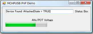
<動作結果>
| PIC側ターゲットボードからの電圧値を8msec毎に読み込み ステータスバーに表示が行なわれている。 |
 |
■ PIC18F4550-PC 間 汎用クラス通信(割り込み方式)
( 自作キバン + Microchip社デモソフト (その2))
マイクロチップDemoBoard(PICDEM FS USB DM163025)($59.99ドル)相当の自作キバンによるUSB通信を行なったので紹介します。
USBフレームワークMCHPFSUSB Framework 2.4にはPICDEMでそのまま動作するPIC側ソフトとPC側ソフトがサンプルソフトとして公開されて
います。汎用クラスの場合PC側のソフトはVC++ と BCBだけとなっています。(VBとC#のサンプルありません。やはり低級な世界はポインタが
必須なのでしょう) PICDEMに対しての変更は下記のみで付属のUSBフレームワークMCHPFSUSB Framework 2.4付属のCDCクラスサンプル
ソフトがそのまま動くようにしました.。ソフトはフレームワークをダウンロードして展開した以下のフォルダのものです。
c:\Microchip Solutions\USB Device - WinUSB - Generic Driver Demo\WinUSB
Simple Demo - Firmware
→PC側ソフト(WinUSBドライバー)
① PIC : PIC18F4550(TQFP) → PIC18F4550(PDIP)
② USBバス電源、ボード電源切り替え回路簡略化
<試作品の仕様>
・PC側とPIC側の通信として、割り込みによるUSB 汎用(Generic)クラス通信を用いる。
・デバイスドライバとしてはWinUSBを使用する
・PCのウィンドウ上のボタンによりPIC側基板上にあるLEDをON/OFFする。
・PIC側キバン上のスイッチをON/OFFした場合のをモニタをPC側ウィンドウ上に表示する。
<試作品回路図>(→回路図のPDFファイル)
PIC18F4550をつかった場合の回路図を以下に示します。
<試作品外観>下記の写真には上記回路図にはない、また本テーマと関係のない部品が多々写っています
   <プログラム例>
以下は、マイクロチップデモキバンPICDEMFSUSBのサンプルソフトに若干のコメントを翻訳、追加したmain.cと一部のusb_device.cです。ソース
コードの変更は行なっていません。
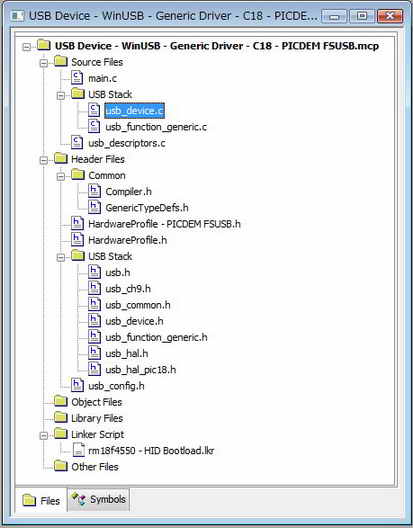
//以下main.c
#include "Compiler.h"
#include "HardwareProfile.h"
#include "GenericTypeDefs.h"
#include "USB/usb_device.h"
#include "USB/usb.h"
#include "USB/usb_function_generic.h"
#include "usb_config.h"

        #pragma config PLLDIV   = 5         // (20 MHz crystal on PICDEM FS USB board)
        #pragma config CPUDIV   = OSC1_PLL2
        #pragma config USBDIV   = 2         // Clock source from 96MHz PLL/2
        #pragma config FOSC     = HSPLL_HS
        #pragma config FCMEN    = OFF
        #pragma config IESO     = OFF
        #pragma config PWRT     = OFF
        #pragma config BOR      = ON
        #pragma config BORV     = 3
        #pragma config VREGEN   = ON      //USB Voltage Regulator
        #pragma config WDT      = OFF
        #pragma config WDTPS    = 32768
        #pragma config MCLRE    = ON
        #pragma config LPT1OSC  = OFF
        #pragma config PBADEN   = OFF
//      #pragma config CCP2MX   = ON
        #pragma config STVREN   = ON
        #pragma config LVP      = OFF
//      #pragma config ICPRT    = OFF       // Dedicated In-Circuit Debug/Programming
        #pragma config XINST    = OFF       // Extended Instruction Set
        #pragma config CP0      = OFF
        #pragma config CP1      = OFF
//      #pragma config CP2      = OFF
//      #pragma config CP3      = OFF
        #pragma config CPB      = OFF
//      #pragma config CPD      = OFF
        #pragma config WRT0     = OFF
        #pragma config WRT1     = OFF
//      #pragma config WRT2     = OFF
//      #pragma config WRT3     = OFF
        #pragma config WRTB     = OFF       // Boot Block Write Protection
        #pragma config WRTC     = OFF
//      #pragma config WRTD     = OFF
        #pragma config EBTR0    = OFF
        #pragma config EBTR1    = OFF
//      #pragma config EBTR2    = OFF
//      #pragma config EBTR3    = OFF
        #pragma config EBTRB    = OFF

/** VARIABLES ******************************************************/
#if defined(__18F14K50) || defined(__18F13K50) || defined(__18LF14K50) || defined(__18LF13K50)
    #pragma udata usbram2
#elif defined(__18F2455) || defined(__18F2550) || defined(__18F4455) || defined(__18F4550)\
    || defined(__18F2458) || defined(__18F2453) || defined(__18F4558) || defined(__18F4553)
    #pragma udata USB_VARIABLES=0x500
#elif defined(__18F4450) || defined(__18F2450)
    #pragma udata USB_VARIABLES=0x480
#else
    #pragma udata
#endif


unsigned char OUTPacket[64];    //PCからの受信バッファー
unsigned char INPacket[64];             //PCへの送信バッファー

BOOL blinkStatusValid;
USB_HANDLE USBGenericOutHandle; //送信ハンドル
USB_HANDLE USBGenericInHandle;  //受信ハンドル

static void InitializeSystem(void);
void USBDeviceTasks(void);
void YourHighPriorityISRCode(void);
void YourLowPriorityISRCode(void);
void UserInit(void);
void ProcessIO(void);
void BlinkUSBStatus(void);


// If no bootloader is used, edit the HardwareProfile - PICDEM FSUSB.h
//file and comment out the following defines:
//#define PROGRAMMABLE_WITH_USB_HID_BOOTLOADER
//#define PROGRAMMABLE_WITH_USB_LEGACY_CUSTOM_CLASS_BOOTLOADER
#define REMAPPED_RESET_VECTOR_ADDRESS                   0x00
#define REMAPPED_HIGH_INTERRUPT_VECTOR_ADDRESS  0x08
#define REMAPPED_LOW_INTERRUPT_VECTOR_ADDRESS   0x18

#pragma code REMAPPED_HIGH_INTERRUPT_VECTOR = REMAPPED_HIGH_INTERRUPT_VECTOR_ADDRESS
void Remapped_High_ISR (void)
{
     _asm goto YourHighPriorityISRCode _endasm
}

#pragma code REMAPPED_LOW_INTERRUPT_VECTOR = REMAPPED_LOW_INTERRUPT_VECTOR_ADDRESS
void Remapped_Low_ISR (void)
{
     _asm goto YourLowPriorityISRCode _endasm
}

#pragma interrupt YourHighPriorityISRCode
void YourHighPriorityISRCode()          //USBデバイスチェックを割り込みで処理
{
        USBDeviceTasks();
}

#pragma interruptlow YourLowPriorityISRCode
void YourLowPriorityISRCode()
{
}


void main(void)
{
    InitializeSystem();
        USBDeviceAttach();

    while(1)
    {
                ProcessIO();    //ユーザ関数
    }
}


static void InitializeSystem(void)
{
        ADCON1 |= 0x0F;                 // デフォルトのピンはすべてデジタルである

        #if defined(USE_USB_BUS_SENSE_IO)       //USBバス電圧検出
    tris_usb_bus_sense = INPUT_PIN; // See HardwareProfile.h
    #endif

    #if defined(USE_SELF_POWER_SENSE_IO)//ボードのセルフ電圧検出
    tris_self_power = INPUT_PIN;        // See HardwareProfile.h
    #endif

        USBGenericOutHandle = 0;        //USB送信ハンドル初期化
        USBGenericInHandle = 0;         //USB受信ハンドル初期化

    UserInit();         //ユーザーアプリ関係初期化  See user.c

    USBDeviceInit();    //USBモジュールのSFRとファームウェア初期化 usb_device.c.
}

void UserInit(void)             //ユーザーアプリ関係初期化  See user.c
{
    mInitAllLEDs();             //LED
    mInitAllSwitches(); //スイッチ

        blinkStatusValid = TRUE;        //LEDは初期状態:点灯
}

void ProcessIO(void)    //ユーザ関数
{
    if(blinkStatusValid)        //LEDの点滅制御
    {
        BlinkUSBStatus();
    }

        //ユーザーのアプリケーションはすべてのデバイスが列挙されるまではデバイスの読み書きはしてはならない
        //デバイスがすべて列挙されてるとUSBDeviceStateにCONFIGURED_STATEがセットされる
    //Note: The user application should not begin attempting to read/write over the USB
    //until after the device has been fully enumerated.  After the device is fully
    //enumerated, the USBDeviceState will be set to "CONFIGURED_STATE".
    if((USBDeviceState < CONFIGURED_STATE)||(USBSuspendControl==1)) return;

        //デバイスが列挙プロセスを終了するとUSBCBInitEP()関数(コールバック関数)が呼び出される。
        //この関数の中でアプリケーションのエンドポイントは初期化される。USBGenRead()関数はエンドポイントからホスト
        //データを取得する。
    //As the device completes the enumeration process, the USBCBInitEP() function will
    //get called.  In this function, we initialize the user application endpoints (in this
    //example code, the user application makes use of endpoint 1 IN and endpoint 1 OUT).
    //The USBGenRead() function call in the USBCBInitEP() function initializes endpoint 1 OUT
    //and "arms" it so that it can receive a packet of data from the host.  Once the endpoint
    //has been armed, the host can then send data to it (assuming some kind of application software
    //is running on the host, and the application software tries to send data to the USB device).

        //ホストがエンドポイントにデータを送るとSIEは自動的にデータを保存する。この保存されたデータはUSBGenRead()関数で取得することができる。
        //エンドポイントにデータが保存されるとエンドポイントハンドルはビジーでなくなる。
    //If the host sends a packet of data to the endpoint 1 OUT buffer, the hardware of the SIE will
    //automatically receive it and store the data at the memory location pointed to when we called
    //USBGenRead().  Additionally, the endpoint handle (in this case USBGenericOutHandle) will indicate
    //that the endpoint is no longer busy.  At this point, it is safe for this firmware to begin reading
    //from the endpoint buffer, and processing the data.  In this example, we have implemented a few very
    //simple commands.  For example, if the host sends a packet of data to the endpoint 1 OUT buffer, with the
    //first byte = 0x80, this is being used as a command to indicate that the firmware should "Toggle LED(s)".

         if(!USBHandleBusy(USBGenericOutHandle))                //エンドポイントがホストデータを取得した場合
    {
        switch(OUTPacket[0])            //受信データパケットのチェック
        {
            case 0x80:  //LED点灯/消灯制御子コマンドの場合
                blinkStatusValid = FALSE;               //通常のLED点滅制御モード:OFF.
                if(mGetLED_1() == mGetLED_2())
                {
                    mLED_1_Toggle();
                    mLED_2_Toggle();
                }
                else
                {
                    mLED_1_On();
                    mLED_2_On();
                }
                break;
            case 0x81:  //プッシュスイッチ状態検出コマンドの場合
                INPacket[0] = 0x81;     //エコーバック
                                if(sw2 == 1)            //プッシュスイッチSW2が押されていない場合
                                {
                                        INPacket[1] = 0x01;
                                }
                                else                    //プッシュスイッチsw2が押されている場合
                                {
                                        INPacket[1] = 0x00;
                                }
                                //PCへの送信データで    まだペンディングになっているものがないかチェックする。もし残っているなら完全に前データを送信するまでエンドポイントには書き込みはしたくない。
                                //Now check to make sure no previous attempts to send data to the host are still pending.  If any attemps are still
                                //pending, we do not want to write to the endpoint 1 IN buffer again, until the previous transaction is complete.
                                //Otherwise the unsent data waiting in the buffer will get overwritten and will result in unexpected behavior.

                                 if(!USBHandleBusy(USBGenericInHandle))         //送信エンドポイントはビジーか?    データは残っていないか?
                    {                                                                                   //ビジー:未送信データあり他   ビジーでない:未送信データなし
                                USBGenericInHandle = USBGenWrite(USBGEN_EP_NUM,(BYTE*)&INPacket,USBGEN_EP_SIZE);

                }
                break;
        }

                //受信データの読み込み
        //Re-arm the OUT endpoint for the next packet:
            //The USBGenRead() function call "arms" the endpoint (and makes it "busy").  If the endpoint is armed, the SIE will
            //automatically accept data from the host, if the host tries to send a packet of data to the endpoint.  Once a data
            //packet addressed to this endpoint is received from the host, the endpoint will no longer be busy, and the application
            //can read the data which will be sitting in the buffer.
        USBGenericOutHandle = USBGenRead(USBGEN_EP_NUM,(BYTE*)&OUTPacket,USBGEN_EP_SIZE);
                                                                                                //受信データの読み込み
    }
}//end ProcessIO


void BlinkUSBStatus(void)       //LED点滅制御
{
    static WORD led_count=0;

    if(led_count == 0)led_count = 10000U;
    led_count--;

    #define mLED_Both_Off()         {mLED_1_Off();mLED_2_Off();}
    #define mLED_Both_On()          {mLED_1_On();mLED_2_On();}
    #define mLED_Only_1_On()        {mLED_1_On();mLED_2_Off();}
    #define mLED_Only_2_On()        {mLED_1_Off();mLED_2_On();}

    if(USBSuspendControl == 1)
    {
        if(led_count==0)
        {
            mLED_1_Toggle();
            if(mGetLED_1())
            {
                mLED_2_On();
            }
            else
            {
                mLED_2_Off();
            }
        }//end if
    }
    else
    {
        if(USBDeviceState == DETACHED_STATE)
        {
            mLED_Both_Off();
        }
        else if(USBDeviceState == ATTACHED_STATE)
        {
            mLED_Both_On();
        }
        else if(USBDeviceState == POWERED_STATE)
        {
            mLED_Only_1_On();
        }
        else if(USBDeviceState == DEFAULT_STATE)
        {
            mLED_Only_2_On();
        }
        else if(USBDeviceState == ADDRESS_STATE)
        {
            if(led_count == 0)
            {
                mLED_1_Toggle();
                mLED_2_Off();
            }//end if
        }
        else if(USBDeviceState == CONFIGURED_STATE)
        {
            if(led_count==0)
            {
                mLED_1_Toggle();
                if(mGetLED_1())
                {
                    mLED_2_Off();
                }
                else
                {
                    mLED_2_On();
                }
            }//end if
        }//end if(...)
    }//end if(UCONbits.SUSPND...)

}//end BlinkUSBStatus


// ******************************************************************************************************
// ************** USB コールバック関数 ****************************************************************
// ******************************************************************************************************

void USBCBSuspend(void) ////サスペンドモードになるとき設定すべきことを書く関数   ピンの低消費電力化etc
{
}
//---------------------------------------------------------------------------------------------------------

void USBCBWakeFromSuspend(void)//サスペンドモードからの起動時に呼び出される関数
{
}

//---------------------------------------------------------------------------------------------------------
void USBCB_SOF_Handler(void)//この関数は SOFパケットと同期して呼び出される。フルスピードであれば1msec毎によびだされる。
                               //必要があればアプリケーションで使用してもよい
{
}
//---------------------------------------------------------------------------------------------------------
void USBCBErrorHandler(void)//開発段階でのデバック時エラーなどで呼び出される
{
}

//---------------------------------------------------------------------------------------------------------
void USBCBCheckOtherReq(void)   //ホスト(PC)からのSSETUP要求が来た場合によびだされる。
{
}

//---------------------------------------------------------------------------------------------------------
void USBCBStdSetDscHandler(void) //SET_DESCRIPTOR要求がきた場合にこの関数は呼び出される。
                                 //ほとんどのアプリケーションでは使われることはない
{
}

//---------------------------------------------------------------------------------------------------------
void USBCBInitEP(void) //ホスト(PC)からSET_CONFIGURATION 要求がきた場合にこの関数はよびだされる。デバイスの現状に合わせ初期化される。
{
    USBEnableEndpoint(USBGEN_EP_NUM,USB_OUT_ENABLED|USB_IN_ENABLED|USB_HANDSHAKE_ENABLED|USB_DISALLOW_SETUP);
    USBGenericOutHandle = USBGenRead(USBGEN_EP_NUM,(BYTE*)&OUTPacket,USBGEN_EP_SIZE);
}

//---------------------------------------------------------------------------------------------------------
void USBCBSendResume(void)// ホスト(PC)ウェイク待ち時間設定
{
    static WORD delay_count;

    USBResumeControl = 1;                // Start RESUME signaling

    delay_count = 1800U;                // Set RESUME line for 1-13 ms
    do
    {
        delay_count--;
    }while(delay_count);
    USBResumeControl = 0;
}

//---------------------------------------------------------------------------------------------------------
BOOL USER_USB_CALLBACK_EVENT_HANDLER(USB_EVENT event, void *pdata, WORD size)
//この関数はUSBスタックからUSBイベント発生をしらせるために呼び出される。このコールバックはUSB_INTERRUPTオプションが選択された場合に発生する。
{
    switch(event)
    {
        case EVENT_CONFIGURED:
            USBCBInitEP();
            break;
        case EVENT_SET_DESCRIPTOR:
            USBCBStdSetDscHandler();
            break;
        case EVENT_EP0_REQUEST:
            USBCBCheckOtherReq();
            break;
        case EVENT_SOF:
            USBCB_SOF_Handler();
            break;
        case EVENT_SUSPEND:
            USBCBSuspend();
            break;
        case EVENT_RESUME:
            USBCBWakeFromSuspend();
            break;
        case EVENT_BUS_ERROR:
            USBCBErrorHandler();
            break;
        case EVENT_TRANSFER:
            Nop();
            break;
        default:
            break;
    }
    return TRUE;
}


//------------------------------------------------------------------------------------------------------
//-----------------------------------------------------------------------------------------------------
//以下 usb_device.c 抜粋

...

void USBDeviceInit(void)        //USBデバイスの初期化
{
    BYTE i;

    // Clear all USB error flags
    USBClearInterruptRegister(U1EIR);   //

    // Clears all USB interrupts  フラグレジスタ
    USBClearInterruptRegister(U1IR); //UIRレジスタをセットす

        // #if defined(USB_POLLING)  何故かこの  #if defined(USB_POLLING) をコメントアウトしなくてもUSB割り込みは正常にかかる!!

    U1EIE = 0x9F; // USB各種エラー検出割り込みイネーブル(U1EIR = UEIR)  Unmask all USB error interrupts
    U1IE = 0xFB;  // USB割り込みイネーブル(U1IE = UIE) Enable all interrupts except ACTVIE

        // #endif

/*
<参考>
1.  usb_hal_pic18.h
        ・・・
        #define U1IE UIE        //USB       INTERRUPT ENABLE RESISTER(イネーブルレジスタ)
        #define U1IR UIR        //USB       INTERRUPT STATUS RESISTER(フラグレジスタ)
        #define U1EIR UEIR      //USB ERROR INTERRUPT STATUS RESISTER(エラーレジスタ)
        ・・・

2. usb_config.h
        ・・・
        //#define USB_POLLING           //ポーリング制御によるUSB通信
        #define USB_INTERRUPT           //割り込み制御によるUSB通信
        ・・・

*/

    //power up the module
    USBPowerModule();

    //set the address of the BDT (if applicable)
    USBSetBDTAddress(BDT);

    // Reset all of the Ping Pong buffers
    USBPingPongBufferReset = 1;
    USBPingPongBufferReset = 0;

    // Reset to default address
    U1ADDR = 0x00;

    //Clear all of the endpoint control registers
    memset((void*)&U1EP1,0x00,(USB_MAX_EP_NUMBER-1));

    //Clear all of the BDT entries
    for(i=0;i<(sizeof(BDT)/sizeof(BDT_ENTRY));i++)
    {
        BDT[i].Val = 0x00;
    }

    // Initialize EP0 as a Ctrl EP
    U1EP0 = EP_CTRL|USB_HANDSHAKE_ENABLED;

    // Flush any pending transactions
    while(USBTransactionCompleteIF == 1)
    {
        USBClearInterruptFlag(USBTransactionCompleteIFReg,USBTransactionCompleteIFBitNum);
    }

    //clear all of the internal pipe information
    inPipes[0].info.Val = 0;
    outPipes[0].info.Val = 0;
    outPipes[0].wCount.Val = 0;

    // Make sure packet processing is enabled
    USBPacketDisable = 0;

    //Get ready for the first packet
    pBDTEntryIn[0] = (volatile BDT_ENTRY*)&BDT[EP0_IN_EVEN];

    // Clear active configuration
    USBActiveConfiguration = 0;

    //Indicate that we are now in the detached state
    USBDeviceState = DETACHED_STATE;

}// end of USBDeviceInit()

...
<動作結果>
| 項目 | PC側 | PIC側 | ||
| PC側からウィンドウ上のトグルスイッチを クリックして、PIC側キバン上のLEDを ON/OFFしているところです。 |
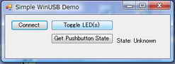 |
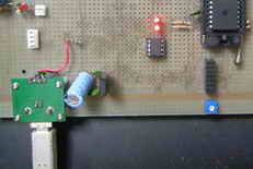 |
||
| PIC側キバン上のスイッチ ON/OFFをモニタしている ところです。 <表示> ONの場合:State Pressed OFFの場合:State Not Pressed |
OFFの場合 | 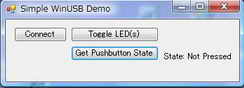 |
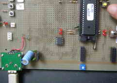 |
|
| ONの場合 | 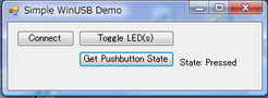 |
|||
■ USB PIC18F4550-PC間 汎用クラス通信(割込み方式、液晶付)
PIC18F4550に液晶を接続した USB通信 送受信の例を紹介します。 → PC側ソフト(VC++)
本ソフトは USBフレームワークMCHPFSUSB Framework 2.4のPICDEMデモボード用サンプルソフトに追加、変更を加えたものです。不足情報は
フレームワークをダウンロードして展開した以下のフォルダのソフトを参照願います。
c:\Microchip Solutions\USB Device - WinUSB - Generic Driver Demo\WinUSB
Simple Demo - Firmware
<試作品仕様>
・PC側からデータをPIC側にUSB 汎用クラス通信で送信する。
・ドラバーはWinUSBドライバーを使用する。
・送信文字コードはシフトJISを使用する
・PIC側では受信した文字列を液晶上段に、受信データに基づき返信したデータを液晶下段に表示する。
・PC側でも受信したデータをリストボックスに表示する。
・PC側からの送信データ 及びPIC側からの返信データは以下とする。
① U.K. → London
② America → Washington
③ Japan → 0x938c(東)0x8b9e(京)
④ I am a boy. → Pardon ?
<試作品回路図> (→回路図のPDFファイル)
PIC18F4550をつかった場合の回路図を以下に示します。
<試作品外観>下記の写真には上記回路図にはない、また本テーマと関係のない部品が多々写っています
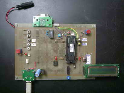
   <プログラム例>

プロジェクトファイルのあるフォルダ
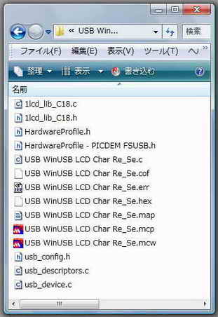
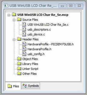
#include "Compiler.h"
#include "HardwareProfile.h"
#include "GenericTypeDefs.h"

#include "usb_device.h"
#include "usb.h"
#include "usb_function_generic.h"


#include "usb_config.h"

#include <stdio.h>
#include <delays.h>
#include <stdio.h>
#include <stdlib.h>
#include <string.h>


#include "1lcd_lib_C18.h"
#include "1lcd_lib_C18.c"

        #pragma config PLLDIV   = 5         // (20 MHz crystal on PICDEM FS USB board)
        #pragma config CPUDIV   = OSC1_PLL2
        #pragma config USBDIV   = 2         // Clock source from 96MHz PLL/2
        #pragma config FOSC     = HSPLL_HS
        #pragma config FCMEN    = OFF
        #pragma config IESO     = OFF
        #pragma config PWRT     = OFF
        #pragma config BOR      = ON
        #pragma config BORV     = 3
        #pragma config VREGEN   = ON      //USB Voltage Regulator
        #pragma config WDT      = OFF
        #pragma config WDTPS    = 32768
        #pragma config MCLRE    = ON
        #pragma config LPT1OSC  = OFF
        #pragma config PBADEN   = OFF
//      #pragma config CCP2MX   = ON
        #pragma config STVREN   = ON
        #pragma config LVP      = OFF
//      #pragma config ICPRT    = OFF       // Dedicated In-Circuit Debug/Programming
        #pragma config XINST    = OFF       // Extended Instruction Set
        #pragma config CP0      = OFF
        #pragma config CP1      = OFF
//      #pragma config CP2      = OFF
//      #pragma config CP3      = OFF
        #pragma config CPB      = OFF
//      #pragma config CPD      = OFF
        #pragma config WRT0     = OFF
        #pragma config WRT1     = OFF
//      #pragma config WRT2     = OFF
//      #pragma config WRT3     = OFF
        #pragma config WRTB     = OFF       // Boot Block Write Protection
        #pragma config WRTC     = OFF
//      #pragma config WRTD     = OFF
        #pragma config EBTR0    = OFF
        #pragma config EBTR1    = OFF
//      #pragma config EBTR2    = OFF
//      #pragma config EBTR3    = OFF
        #pragma config EBTRB    = OFF

/** VARIABLES ******************************************************/
#if defined(__18F14K50) || defined(__18F13K50) || defined(__18LF14K50) || defined(__18LF13K50)
    #pragma udata usbram2
#elif defined(__18F2455) || defined(__18F2550) || defined(__18F4455) || defined(__18F4550)\
    || defined(__18F2458) || defined(__18F2453) || defined(__18F4558) || defined(__18F4553)
    #pragma udata USB_VARIABLES=0x500
#elif defined(__18F4450) || defined(__18F2450)
    #pragma udata USB_VARIABLES=0x480
#else
    #pragma udata
#endif


unsigned char OUTPacket[64];    //PCからの受信バッファー
unsigned char INPacket[64];             //PCへの送信バッファー


char tempBuf[20];
char tempBuf1[20];
char tempBuf2[20];
char tempBuf3[20];


unsigned char* str1;
char* str2;
unsigned char Japan[]   = "Japan           ";
unsigned char UK[]              = "U.K.            ";
unsigned char America[] = "America         ";

//char Tokyo[]      = "Tokyo           \r";
char Tokyo[]            = {0x93,0x8C,0x8B,0x9E,' ',' ',' ',' ',' ',' ',' ',' ',' ',' ',' ',' ','\r'};
                                        //シフトJIS 東[938C]、京[8B9E]


char London[]           = "London          \r";
char Washington[]       = "Washington      \r";
char Pardon[]           = "Pardon ?        \r";

BOOL blinkStatusValid;
USB_HANDLE USBGenericOutHandle; //送信ハンドル
USB_HANDLE USBGenericInHandle;  //受信ハンドル

static void InitializeSystem(void);
void USBDeviceTasks(void);
void YourHighPriorityISRCode(void);
void YourLowPriorityISRCode(void);
void UserInit(void);
void ProcessIO(void);
void BlinkUSBStatus(void);


// If no bootloader is used, edit the HardwareProfile - PICDEM FSUSB.h
//file and comment out the following defines:
//#define PROGRAMMABLE_WITH_USB_HID_BOOTLOADER
//#define PROGRAMMABLE_WITH_USB_LEGACY_CUSTOM_CLASS_BOOTLOADER
#define REMAPPED_RESET_VECTOR_ADDRESS                   0x00
#define REMAPPED_HIGH_INTERRUPT_VECTOR_ADDRESS  0x08
#define REMAPPED_LOW_INTERRUPT_VECTOR_ADDRESS   0x18


void lcd_printf(char* strx)      //液晶表示補助関数
{
        while(*strx)     //文字列終端の '\0'を検出するまで
        {
                lcd_data(*strx);         // 1文字表示
                strx++;
        }
}


#pragma code REMAPPED_HIGH_INTERRUPT_VECTOR = REMAPPED_HIGH_INTERRUPT_VECTOR_ADDRESS
void Remapped_High_ISR (void)
{
     _asm goto YourHighPriorityISRCode _endasm
}

#pragma code REMAPPED_LOW_INTERRUPT_VECTOR = REMAPPED_LOW_INTERRUPT_VECTOR_ADDRESS
void Remapped_Low_ISR (void)
{
     _asm goto YourLowPriorityISRCode _endasm
}

#pragma interrupt YourHighPriorityISRCode
void YourHighPriorityISRCode()          //USBデバイスチェックを割り込みで処理
{
        USBDeviceTasks();
}

#pragma interruptlow YourLowPriorityISRCode
void YourLowPriorityISRCode()
{
}


void main(void)
{
    InitializeSystem();
        USBDeviceAttach();


        TRISBbits.TRISB0=0;     //液晶コントロール端子RB0出力モード
        TRISBbits.TRISB2=0;     //同上RB2出力モード
        TRISAbits.TRISA1 = 1;   //バス電圧検出ポートRA1を入力ポートに設定
        TRISAbits.TRISA2 = 1;   //ボード電源電圧検出ポートRA2を入力ポートに設定

        Delay10KTCYx(200);//400msec液晶立ち上がりを待つ  200KT: 0.05μsec×4×10000×200=400000μsec=400msec

        lcd_init();                             // LCD初期化
    lcd_cmd(0b00001100);        // カーソル:OFF    ブリンク:OFF
    lcd_clear();

        sprintf(tempBuf,"USB6"); //文字列としてバッファーに収納
        lcd_printf(tempBuf);

    lcd_cmd(0xC0);//2行目の先頭へ
        sprintf(tempBuf, "     Start !!");  //文字列としてバッファーに収納
        lcd_printf(tempBuf);


    while(1)
    {
                ProcessIO();    //ユーザ関数
    }
}


static void InitializeSystem(void)
{
        ADCON1 |= 0x0F;                 // デフォルトのピンはすべてデジタルである

        #if defined(USE_USB_BUS_SENSE_IO)       //USBバス電圧検出
    tris_usb_bus_sense = INPUT_PIN; // See HardwareProfile.h
    #endif

    #if defined(USE_SELF_POWER_SENSE_IO)//ボードのセルフ電圧検出
    tris_self_power = INPUT_PIN;        // See HardwareProfile.h
    #endif

        USBGenericOutHandle = 0;        //USB送信ハンドル初期化
        USBGenericInHandle = 0;         //USB受信ハンドル初期化

    UserInit();         //ユーザーアプリ関係初期化  See user.c

    USBDeviceInit();    //USBモジュールのSFRとファームウェア初期化 usb_device.c.
}

void UserInit(void)             //ユーザーアプリ関係初期化  See user.c
{
    mInitAllLEDs();             //LED
    mInitAllSwitches(); //スイッチ
        blinkStatusValid = TRUE;        //LEDは初期状態:点灯
}

void ProcessIO(void)    //ユーザ関数
{

    if(blinkStatusValid)        //LEDの点滅制御
    {
        BlinkUSBStatus();
    }

        //ユーザーのアプリケーションはすべてのデバイスが列挙されるまではデバイスの読み書きはしてはならない
        //デバイスがすべて列挙されてるとUSBDeviceStateにCONFIGURED_STATEがセットされる
        //Note: The user application should not begin attempting to read/write over the USB
        //until after the device has been fully enumerated.  After the device is fully
        //enumerated, the USBDeviceState will be set to "CONFIGURED_STATE".
        if((USBDeviceState < CONFIGURED_STATE)||(USBSuspendControl==1)) return;

        //デバイスが列挙プロセスを終了するとUSBCBInitEP()関数(コールバック関数)が呼び出される。
        //この関数の中でアプリケーションのエンドポイントは初期化される。USBGenRead()関数はエンドポイントからホスト
        //データを取得する。
        //As the device completes the enumeration process, the USBCBInitEP() function will
        //get called.  In this function, we initialize the user application endpoints (in this
        //example code, the user application makes use of endpoint 1 IN and endpoint 1 OUT).
        //The USBGenRead() function call in the USBCBInitEP() function initializes endpoint 1 OUT
        //and "arms" it so that it can receive a packet of data from the host.  Once the endpoint
        //has been armed, the host can then send data to it (assuming some kind of application software
        //is running on the host, and the application software tries to send data to the USB device).

        //ホストがエンドポイントにデータを送るとSIEは自動的にデータを保存する。この保存されたデータはUSBGenRead()関数で取得することができる。
        //エンドポイントにデータが保存されるとエンドポイントハンドルはビジーでなくなる。
        //If the host sends a packet of data to the endpoint 1 OUT buffer, the hardware of the SIE will
        //automatically receive it and store the data at the memory location pointed to when we called
        //USBGenRead().  Additionally, the endpoint handle (in this case USBGenericOutHandle) will indicate
        //that the endpoint is no longer busy.  At this point, it is safe for this firmware to begin reading
        //from the endpoint buffer, and processing the data.  In this example, we have implemented a few very
        //simple commands.  For example, if the host sends a packet of data to the endpoint 1 OUT buffer, with the
        //first byte = 0x80, this is being used as a command to indicate that the firmware should "Toggle LED(s)".

        if(!USBHandleBusy(USBGenericOutHandle))         //エンドポイントがホストデータを取得した場合
        {
                OUTPacket[16] = 0x00;
                str1 = &OUTPacket[0];

                if(strcmp(str1,Japan) == 0)
                {
                        str2 = Tokyo;

                        lcd_cmd(0x80);  //1行目へ
                        sprintf(&tempBuf1,"%s",str1);
                        lcd_printf(&tempBuf1[0]);       //受信データを液晶に表示
                        lcd_cmd(0xC0);  //2行目
                        sprintf(&tempBuf2,"%s",str2);

                        sprintf(&tempBuf3,"%x%x%x%x",Tokyo[0],Tokyo[1],Tokyo[2],Tokyo[3]);
                                                        //sprintf()のバグのため(?)か C18では制御文字の前にffをつける仕様になっているためか
                                                        //液晶には ”ff93ff8Cff8Bff9E” と表示される
                                                        //シフトJIS 東[938C]、京[8B9E]

                        lcd_printf(&tempBuf3[0]);       //送信データを液晶に表示
                }
                else if(strcmp(str1,UK) == 0)
                {
                        str2 = London;
                        lcd_cmd(0x80);  //1行目へ
                        sprintf(&tempBuf1,"%s",str1);
                        lcd_printf(&tempBuf1[0]);       //受信データを液晶に表示
                        lcd_cmd(0xC0);  //2行目
                        sprintf(&tempBuf2,"%s",str2);
                        lcd_printf(&tempBuf2[0]);       //送信データを液晶に表示
                }
                else if(strcmp(str1,America) == 0)
                {
                        str2 = Washington;
                        lcd_cmd(0x80);  //1行目へ
                        sprintf(&tempBuf1,"%s",str1);
                        lcd_printf(&tempBuf1[0]);       //受信データを液晶に表示
                        lcd_cmd(0xC0);  //2行目
                        sprintf(&tempBuf2,"%s",str2);
                        lcd_printf(&tempBuf2[0]);       //送信データを液晶に表示
                }
                else
                {
                        str2 = Pardon;
                        lcd_cmd(0x80);  //1行目へ
                        sprintf(&tempBuf1,"%s",str1);
                        lcd_printf(&tempBuf1[0]);       //受信データを液晶に表示
                        lcd_cmd(0xC0);  //2行目
                        sprintf(&tempBuf2,"%s",str2);
                        lcd_printf(&tempBuf2[0]);       //送信データを液晶に表示
                }

                if(!USBHandleBusy(USBGenericInHandle))          //送信エンドポイントはビジーか?    データは残っていないか?
                {                                                                                       //ビジー:未送信データあり他   ビジーでない:未送信データなし
                        USBGenericInHandle = USBGenWrite(USBGEN_EP_NUM,(BYTE*)&tempBuf2,USBGEN_EP_SIZE);
                }
                        //受信データの読み込み
                //Re-arm the OUT endpoint for the next packet:
                        //The USBGenRead() function call "arms" the endpoint (and makes it "busy").  If the endpoint is armed, the SIE will
                //automatically accept data from the host, if the host tries to send a packet of data to the endpoint.  Once a data
                //packet addressed to this endpoint is received from the host, the endpoint will no longer be busy, and the application
                //can read the data which will be sitting in the buffer.
                USBGenericOutHandle = USBGenRead(USBGEN_EP_NUM,(BYTE*)&OUTPacket,USBGEN_EP_SIZE);
                                                                        //受信データの読み込み
    }
}//end ProcessIO


void BlinkUSBStatus(void)       //LED点滅制御
{
    static WORD led_count=0;

    if(led_count == 0)led_count = 10000U;
    led_count--;

    #define mLED_Both_Off()         {mLED_1_Off();mLED_2_Off();}
    #define mLED_Both_On()          {mLED_1_On();mLED_2_On();}
    #define mLED_Only_1_On()        {mLED_1_On();mLED_2_Off();}
    #define mLED_Only_2_On()        {mLED_1_Off();mLED_2_On();}

    if(USBSuspendControl == 1)
    {
        if(led_count==0)
        {
            mLED_1_Toggle();
            if(mGetLED_1())
            {
                mLED_2_On();
            }
            else
            {
                mLED_2_Off();
            }
        }//end if
    }
    else
    {
        if(USBDeviceState == DETACHED_STATE)
        {
            mLED_Both_Off();
        }
        else if(USBDeviceState == ATTACHED_STATE)
        {
            mLED_Both_On();
        }
        else if(USBDeviceState == POWERED_STATE)
        {
            mLED_Only_1_On();
        }
        else if(USBDeviceState == DEFAULT_STATE)
        {
            mLED_Only_2_On();
        }
        else if(USBDeviceState == ADDRESS_STATE)
        {
            if(led_count == 0)
            {
                mLED_1_Toggle();
                mLED_2_Off();
            }//end if
        }
        else if(USBDeviceState == CONFIGURED_STATE)
        {
            if(led_count==0)
            {
                mLED_1_Toggle();
                if(mGetLED_1())
                {
                    mLED_2_Off();
                }
                else
                {
                    mLED_2_On();
                }
            }//end if
        }//end if(...)
    }//end if(UCONbits.SUSPND...)

}//end BlinkUSBStatus


// ******************************************************************************************************
// ************** USB コールバック関数 ****************************************************************
// ******************************************************************************************************

void USBCBSuspend(void) ////サスペンドモードになるとき設定すべきことを書く関数   ピンの低消費電力化etc
{
}
//---------------------------------------------------------------------------------------------------------

void USBCBWakeFromSuspend(void)//サスペンドモードからの起動時に呼び出される関数
{
}

//---------------------------------------------------------------------------------------------------------
void USBCB_SOF_Handler(void)//この関数は SOFパケットと同期して呼び出される。フルスピードであれば1msec毎によびだされる。
                               //必要があればアプリケーションで使用してもよい
{
}
//---------------------------------------------------------------------------------------------------------
void USBCBErrorHandler(void)//開発段階でのデバック時エラーなどで呼び出される
{
}

//---------------------------------------------------------------------------------------------------------
void USBCBCheckOtherReq(void)   //ホスト(PC)からのSSETUP要求が来た場合によびだされる。
{
}

//---------------------------------------------------------------------------------------------------------
void USBCBStdSetDscHandler(void) //SET_DESCRIPTOR要求がきた場合にこの関数は呼び出される。
                                 //ほとんどのアプリケーションでは使われることはない
{
}

//---------------------------------------------------------------------------------------------------------
void USBCBInitEP(void) //ホスト(PC)からSET_CONFIGURATION 要求がきた場合にこの関数はよびだされる。デバイスの現状に合わせ初期化される。
{
    USBEnableEndpoint(USBGEN_EP_NUM,USB_OUT_ENABLED|USB_IN_ENABLED|USB_HANDSHAKE_ENABLED|USB_DISALLOW_SETUP);
    USBGenericOutHandle = USBGenRead(USBGEN_EP_NUM,(BYTE*)&OUTPacket,USBGEN_EP_SIZE);
}

//---------------------------------------------------------------------------------------------------------
void USBCBSendResume(void)// ホスト(PC)ウェイク待ち時間設定
{
    static WORD delay_count;

    USBResumeControl = 1;                // Start RESUME signaling

    delay_count = 1800U;                // Set RESUME line for 1-13 ms
    do
    {
        delay_count--;
    }while(delay_count);
    USBResumeControl = 0;
}

//---------------------------------------------------------------------------------------------------------
BOOL USER_USB_CALLBACK_EVENT_HANDLER(USB_EVENT event, void *pdata, WORD size)
//この関数はUSBスタックからUSBイベント発生をしらせるために呼び出される。このコールバックはUSB_INTERRUPTオプションが選択された場合に発生する。
{
    switch(event)
    {
        case EVENT_CONFIGURED:
            USBCBInitEP();
            break;
        case EVENT_SET_DESCRIPTOR:
            USBCBStdSetDscHandler();
            break;
        case EVENT_EP0_REQUEST:
            USBCBCheckOtherReq();
            break;
        case EVENT_SOF:
            USBCB_SOF_Handler();
            break;
        case EVENT_SUSPEND:
            USBCBSuspend();
            break;
        case EVENT_RESUME:
            USBCBWakeFromSuspend();
            break;
        case EVENT_BUS_ERROR:
            USBCBErrorHandler();
            break;
        case EVENT_TRANSFER:
            Nop();
            break;
        default:
            break;
    }
    return TRUE;
}


//------------------------------------------------------------------------------------------------------
//-----------------------------------------------------------------------------------------------------
//以下 usb_device.c 抜粋

...

void USBDeviceInit(void)        //USBデバイスの初期化
{
    BYTE i;

    // Clear all USB error flags
    USBClearInterruptRegister(U1EIR);   //

    // Clears all USB interrupts  フラグレジスタ
    USBClearInterruptRegister(U1IR); //UIRレジスタをセットす

        // #if defined(USB_POLLING)  何故かこの  #if defined(USB_POLLING) をコメントアウトしなくてもUSB割り込みは正常にかかる!!

    U1EIE = 0x9F; // USB各種エラー検出割り込みイネーブル(U1EIR = UEIR)  Unmask all USB error interrupts
    U1IE = 0xFB;  // USB割り込みイネーブル(U1IE = UIE) Enable all interrupts except ACTVIE

        // #endif

/*
<参考>
1.  usb_hal_pic18.h
        ・・・
        #define U1IE UIE        //USB       INTERRUPT ENABLE RESISTER(イネーブルレジスタ)
        #define U1IR UIR        //USB       INTERRUPT STATUS RESISTER(フラグレジスタ)
        #define U1EIR UEIR      //USB ERROR INTERRUPT STATUS RESISTER(エラーレジスタ)
        ・・・

2. usb_config.h
        ・・・
        //#define USB_POLLING           //ポーリング制御によるUSB通信
        #define USB_INTERRUPT           //割り込み制御によるUSB通信
        ・・・

*/

    //power up the module
    USBPowerModule();

    //set the address of the BDT (if applicable)
    USBSetBDTAddress(BDT);

    // Reset all of the Ping Pong buffers
    USBPingPongBufferReset = 1;
    USBPingPongBufferReset = 0;

    // Reset to default address
    U1ADDR = 0x00;

    //Clear all of the endpoint control registers
    memset((void*)&U1EP1,0x00,(USB_MAX_EP_NUMBER-1));

    //Clear all of the BDT entries
    for(i=0;i<(sizeof(BDT)/sizeof(BDT_ENTRY));i++)
    {
        BDT[i].Val = 0x00;
    }

    // Initialize EP0 as a Ctrl EP
    U1EP0 = EP_CTRL|USB_HANDSHAKE_ENABLED;

    // Flush any pending transactions
    while(USBTransactionCompleteIF == 1)
    {
        USBClearInterruptFlag(USBTransactionCompleteIFReg,USBTransactionCompleteIFBitNum);
    }

    //clear all of the internal pipe information
    inPipes[0].info.Val = 0;
    outPipes[0].info.Val = 0;
    outPipes[0].wCount.Val = 0;

    // Make sure packet processing is enabled
    USBPacketDisable = 0;

    //Get ready for the first packet
    pBDTEntryIn[0] = (volatile BDT_ENTRY*)&BDT[EP0_IN_EVEN];

    // Clear active configuration
    USBActiveConfiguration = 0;

    //Indicate that we are now in the detached state
    USBDeviceState = DETACHED_STATE;

}// end of USBDeviceInit()
<動作結果>
| PC側Window | PIC側液晶画面 | ||
| <送信前> |
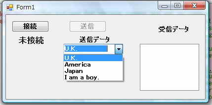 |
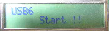 |
|
| <送信後> ”接続ボタン”をクリック後順次下記をコンボビックスから選択して送信した結果 ① U..K. ② Amerrica ③ Japan ④ I am a boy. (注) Japanを送信した時にPIC側から実際に返信されるデータは、 0x938c(東)0x8b9e(京)です。 ffはコンパイラC18のバグ(?)か、制御文字の場合の仕様によるもので実際には送信データに含まれていません。 |
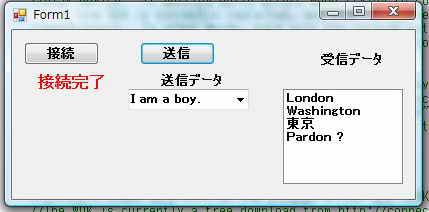 |
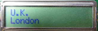 |
|
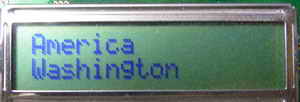 |
|||
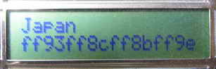 |
|||
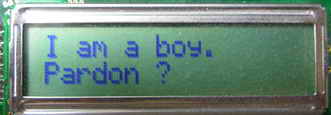 |
■ USB PIC18F4550-PC間 Mass Strage クラス通信(SDカード読み書き)
(1) マイクロチップ 第1世代SDカードライブラリー版(仮称)
Mass Strage Class(マスストレージクラス)はPICにSDカードやマルチメディアカードを接続してUSB通信をすることによりカードが読み書きできる
ライブラリクラスです。 読み書きできるファイルフォーマットは、FAT16、FAT32、NTFSです。
以下に 同ライブリのMicrochip USB C18 Firmware Version 1.0を若干修正してPIC18F4550で動作させた例を紹介します。
<試作品仕様>
・PIC18F4550にSDカードを接続して、PCからSDカード内のファイルを読み書きする。
・USB接続が正常におなわれたらLEDを約1秒周期で点滅する。
<試作品回路図> (→回路図のPDFファイル)
PIC18F4550をつかった場合の回路図を以下に示します。
<試作品外観>下記の写真には上記回路図にはない、また本テーマと関係のない部品が多々写っています
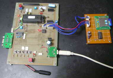
<プログラム例>
//  SDカード読み書き
//下記のプログラムは Microchip USB C18 Firmware Version 1.0 を一部変更したものです。
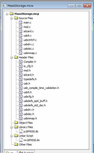
/*********************************************************************
 *
 *                Microchip USB C18 Firmware Version 1.0
 *
 *********************************************************************
 * FileName:        main.c
 * Dependencies:    See INCLUDES section below
 * Processor:       PIC18
 * Compiler:        C18 2.30.01+
 * Company:         Microchip Technology, Inc.
 *
 * Software License Agreement
 *
 * The software supplied herewith by Microchip Technology Incorporated
 * (the 鼎ompany・ for its PICmicroョ Microcontroller is intended and
 * supplied to you, the Company痴 customer, for use solely and
 * exclusively on Microchip PICmicro Microcontroller products. The
 * software is owned by the Company and/or its supplier, and is
 * protected under applicable copyright laws. All rights are reserved.
 * Any use in violation of the foregoing restrictions may subject the
 * user to criminal sanctions under applicable laws, as well as to
 * civil liability for the breach of the terms and conditions of this
 * license.
 *
 * THIS SOFTWARE IS PROVIDED IN AN 鄭S IS・CONDITION. NO WARRANTIES,
 * WHETHER EXPRESS, IMPLIED OR STATUTORY, INCLUDING, BUT NOT LIMITED
 * TO, IMPLIED WARRANTIES OF MERCHANTABILITY AND FITNESS FOR A
 * PARTICULAR PURPOSE APPLY TO THIS SOFTWARE. THE COMPANY SHALL NOT,
 * IN ANY CIRCUMSTANCES, BE LIABLE FOR SPECIAL, INCIDENTAL OR
 * CONSEQUENTIAL DAMAGES, FOR ANY REASON WHATSOEVER.
 *
 * Author               Date        Comment
 *~~~~~~~~~~~~~~~~~~~~~~~~~~~~~~~~~~~~~~~~~~~~~~~~~~~~~~~~~~~~~~~~~~~~
 * Rawin Rojvanit       11/19/04    Original.
 ********************************************************************/

/** I N C L U D E S **********************************************************/
#include <p18f4550.h>
//#include <p18cxxx.h>
//#include "system\sdcard\sdcard.h"
#include "system\typedefs.h"                        // Required
#include "system\usb\usb.h"                         // Required
#include "io_cfg.h"                                 // Required

#include "system\usb\usb_compile_time_validation.h" // Optional
//#include "user\user_mouse.h"                        // Modifiable

/** V A R I A B L E S ********************************************************/
#pragma udata
unsigned int time;


/** P R I V A T E  P R O T O T Y P E S ***************************************/
static void InitializeSystem(void);
void USBTasks(void);


/** V E C T O R  R E M A P P I N G *******************************************/

/*
extern void _startup (void);        // See c018i.c in your C18 compiler dir

#pragma code _RESET_INTERRUPT_VECTOR = 0x000800
void _reset (void)
{
    _asm goto _startup _endasm
}
#pragma code


*/


/** D E C L A R A T I O N S **************************************************/
#pragma code
/******************************************************************************
 * Function:        void main(void)
 *
 * PreCondition:    None
 *
 * Input:           None
 *
 * Output:          None
 *
 * Side Effects:    None
 *
 * Overview:        Main program entry point.
 *
 * Note:            None
 *****************************************************************************/
void main(void)
{

        // TEST RTC and CTS
        /*
                // variable
                volatile unsigned long delay;

                // Test CTS and RTS
                // RTS - for MAX3232 output, for PIC - RA3 - input
                TRISAbits.TRISA3 = 1;

                // CTS - for MAX3232 input, for PIC - RA2 - output
                TRISAbits.TRISA2 = 0;
                // Low
                LATAbits.LATA2 = 0;


                // Led - output
                TRISDbits.TRISD3 = 0;
                // Low
                LATDbits.LATD3 = 0;

                // All as input
                ADCON1 = 0x0F;


                // loop
                while(1) {

                        LATAbits.LATA2 ^= 1;

                        for(delay=0; delay<50000; delay++) {

                                if(((PORTAbits.RA3)==1)) {
                                        LATDbits.LATD3 = 1;
                                }
                                else {
                                        LATDbits.LATD3 = 0;
                                }
                        }
                }
        */

        // CP
//      TRISBbits.TRISB4 = 1;
//      while(PORTBbits.RB4) for(time=0; time<5000; time++);

    InitializeSystem();


    while(1)
    {

        USBTasks();         // USB Tasks
        ProcessIO();        // See msd.c & msd.h
    } //end while
}//end main

/******************************************************************************
 * Function:        static void InitializeSystem(void)
 *
 * PreCondition:    None
 *
 * Input:           None
 *
 * Output:          None
 *
 * Side Effects:    None
 *
 * Overview:        InitializeSystem is a centralize initialization routine.
 *                  All required USB initialization routines are called from
 *                  here.
 *
 *                  User application initialization routine should also be
 *                  called from here.
 *
 * Note:            None
 *****************************************************************************/
static void InitializeSystem(void)
{
    ADCON1 |= 0x0F;                 // Default all pins to digital

    #if defined(USE_USB_BUS_SENSE_IO)
    tris_usb_bus_sense = INPUT_PIN; // See io_cfg.h
    #endif

    #if defined(USE_SELF_POWER_SENSE_IO)
    tris_self_power = INPUT_PIN;
    #endif
    mInitializeUSBDriver();         // See usbdrv.h

        // SLA
        // UCFG &= ~(_PUEN);
        // SLA

                // CP
        TRISBbits.TRISB4 = 1;
        while(PORTBbits.RB4) for(time=0; time<5000; time++);

    SDCardInit();                     // See msd.c & .h

}//end InitializeSystem

/******************************************************************************
 * Function:        void USBTasks(void)
 *
 * PreCondition:    InitializeSystem has been called.
 *
 * Input:           None
 *
 * Output:          None
 *
 * Side Effects:    None
 *
 * Overview:        Service loop for USB tasks.
 *
 * Note:            None
 *****************************************************************************/
void USBTasks(void)
{
    /*
     * Servicing Hardware
     */
    USBCheckBusStatus();                    // Must use polling method
    if(UCFGbits.UTEYE!=1)
        USBDriverService();                 // Interrupt or polling method

}// end USBTasks


/** EOF main.c ***************************************************************/


//本ライブラリは マスストレージクラスのライブラリとしては旧バージョンとなるのでマイクロチップのUSBサイトでは
//見つけにくい状態ですが、市販のトレーニングキット(例: OLIMEX社 PIC18F4550マイコンコンボード PIC-USB-STK
//(日本販売代理店(㈱ストロベリーリナックス))などの中にみつけることができます。
///またマニュアル等参考技術資料は、マイクロチップUSBサイト  及びMicrochip Applications Libraryにあります。
<動作結果>
| モード | PCの画面 |
|
| ① | USBプラグを試作品に挿入 → PCが試作品を認識 |
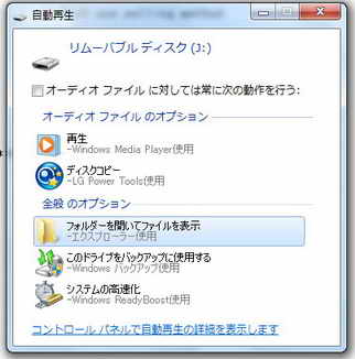 |
| ② | エクスプローラで SDカードの内容を表示 |
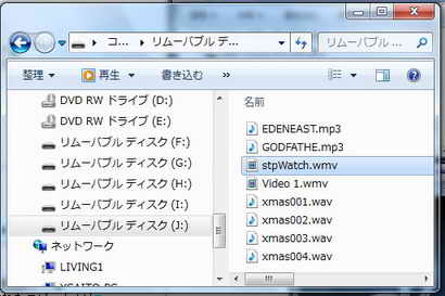 |
| ③ | 音声ファイルのWAVファイルを メディアプレーヤーで実行 →PCに接続されたスピーカより 連続的なスムーズな音(音楽)が発生 |
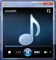 |
動画ファイルのWMVファイルを メディアプレーヤで実行 → 連続的なスムーズなQVGAの動画を再生 |
 |
<追記>
★ PCがターゲットボードを認識しなくなった場合、PCのUSBポートを変更すると認識するようになることがあります。
★ PICのソフトに問題がある場合PCが不調になる可能性があります。復元ポイントを設定後実験に着手することをおすすめします。Windowsは
正常モードからたち上がらなくなった場合、セーフモードから復元ポイントに戻すこともできます。
(2) マイクロチップ 第2世代SDカードライブラリー版 (仮称)
Mass Strage Class(マスストレージクラス)はPICにSDカードやマルチメディアカードを接続してUSB通信をすることによりカードが読み書きできる
ライブラリクラスです。 読み書きできるファイルフォーマットは、FAT16、FAT32、NTFSです。
以下に Microchip Memory Disk Drive File System(マイクロチップ 第2世代SDカードライブラリー版の PIC18F87J50用のサンプルコードをもとに
PIC18F4550用に変更して動作させた例を紹介します。
<試作品仕様>
・PIC18F4550にSDカードを接続して、PCからSDカード内のファイルを読み書きする。
<試作品回路図> (→回路図のPDFファイル)
PIC18F4550をつかった場合の回路図を以下に示します。
<試作品外観>下記の写真には上記回路図にはない、また本テーマと関係のない部品が多々写っています
   <プログラム例>
//  マイクロチップ 第2世代SDライブラリー版 (仮称)
//              SDカード読み書き (PIC18F4550)
//
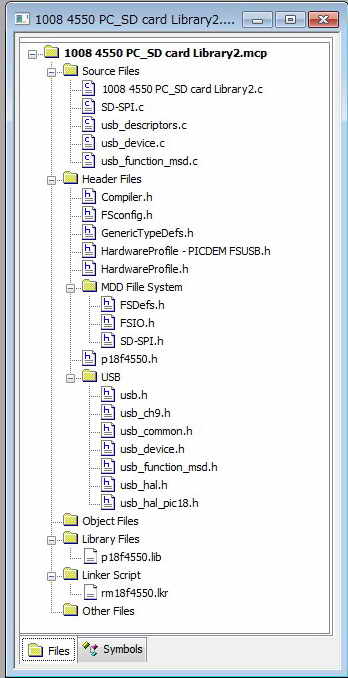
#include <p18f4550.h>

#include "USB/USB.h"
#include "./USB/usb_function_msd.h"

#include "HardwareProfile.h"
#include "MDD File System\SD-SPI.h"

        #pragma config PLLDIV   = 5         // (20 MHz crystal on PICDEM FS USB board)
        #pragma config CPUDIV   = OSC1_PLL2
        #pragma config USBDIV   = 2         // Clock source from 96MHz PLL/2
        #pragma config FOSC     = HSPLL_HS
        #pragma config FCMEN    = OFF
        #pragma config IESO     = OFF
        #pragma config PWRT     = OFF
        #pragma config BOR      = ON
        #pragma config BORV     = 3
        #pragma config VREGEN   = ON      //USB Voltage Regulator
        #pragma config WDT      = OFF
        #pragma config WDTPS    = 32768
        #pragma config MCLRE    = ON
        #pragma config LPT1OSC  = OFF
        #pragma config PBADEN   = OFF
//      #pragma config CCP2MX   = ON
        #pragma config STVREN   = ON
        #pragma config LVP      = OFF
//      #pragma config ICPRT    = OFF       // Dedicated In-Circuit Debug/Programming
        #pragma config XINST    = OFF       // Extended Instruction Set
        #pragma config CP0      = OFF
        #pragma config CP1      = OFF
//      #pragma config CP2      = OFF
//      #pragma config CP3      = OFF
        #pragma config CPB      = OFF
//      #pragma config CPD      = OFF
        #pragma config WRT0     = OFF
        #pragma config WRT1     = OFF
//      #pragma config WRT2     = OFF
//      #pragma config WRT3     = OFF
        #pragma config WRTB     = OFF       // Boot Block Write Protection
        #pragma config WRTC     = OFF
//      #pragma config WRTD     = OFF
        #pragma config EBTR0    = OFF
        #pragma config EBTR1    = OFF
//      #pragma config EBTR2    = OFF
//      #pragma config EBTR3    = OFF
        #pragma config EBTRB    = OFF


/// Standard Response to INQUIRY command stored in ROM
const ROM InquiryResponse inq_resp = {
        0x00,           // peripheral device is connected, direct access block device
        0x80,           // removable
        0x04,           // version = 00=> does not conform to any standard, 4=> SPC-2
        0x02,           // response is in format specified by SPC-2
        0x20,           // n-4 = 36-4=32= 0x20
        0x00,           // sccs etc.
        0x00,           // bque=1 and cmdque=0,indicates simple queueing 00 is obsolete,
                        // but as in case of other device, we are just using 00
        0x00,           // 00 obsolete, 0x80 for basic task queueing
        {'M','i','c','r','o','c','h','p'
    },
        // this is the T10 assigned Vendor ID
        {'M','a','s','s',' ','S','t','o','r','a','g','e',' ',' ',' ',' '
    },
        {'0','0','0','1'
    }
};


static void InitializeSystem(void);
void USBDeviceTasks(void);
void ProcessIO(void);
void YourHighPriorityISRCode(void);
void YourLowPriorityISRCode(void);


void main(void)
{
        InitializeSystem();     //システム初期化
        USBDeviceAttach();      //接続再確認    //usb_device.c 参照

    while(1)
    {
                USBDeviceTasks();       //ポーリングチェック
                ProcessIO();            //ユーザ関数
    }

}

//  以下 サンプルコードmain.c と同じ


//******************************************************************************
//******************************************************************************
//******************************************************************************

//変更を加えたファイル HardwareProfile.h
/********************************************************************
 FileName:      HardwareProfile.h
 Dependencies:  See INCLUDES section
 Processor:     PIC18, PIC24, or PIC32 USB Microcontrollers
 Hardware:      The code is natively intended to be used on the
                  following hardware platforms:
                    PICDEM・FS USB Demo Board
                    PIC18F46J50 FS USB Plug-In Module
                    PIC18F87J50 FS USB Plug-In Module
                    Explorer 16 + PIC24 or PIC32 USB PIMs
                    PIC24F Starter Kit
                    Low Pin Count USB Development Kit
                  The firmware may be modified for use on other USB
                    platforms by editing this file (HardwareProfile.h)
 Compiler:      Microchip C18 (for PIC18), C30 (for PIC24),
                  or C32 (for PIC32)
 Company:       Microchip Technology, Inc.

 Software License Agreement:

 The software supplied herewith by Microchip Technology Incorporated
 (the 鼎ompany・ for its PICョ Microcontroller is intended and
 supplied to you, the Company痴 customer, for use solely and
 exclusively on Microchip PIC Microcontroller products. The
 software is owned by the Company and/or its supplier, and is
 protected under applicable copyright laws. All rights are reserved.
 Any use in violation of the foregoing restrictions may subject the
 user to criminal sanctions under applicable laws, as well as to
 civil liability for the breach of the terms and conditions of this
 license.

 THIS SOFTWARE IS PROVIDED IN AN 鄭S IS・CONDITION. NO WARRANTIES,
 WHETHER EXPRESS, IMPLIED OR STATUTORY, INCLUDING, BUT NOT LIMITED
 TO, IMPLIED WARRANTIES OF MERCHANTABILITY AND FITNESS FOR A
 PARTICULAR PURPOSE APPLY TO THIS SOFTWARE. THE COMPANY SHALL NOT,
 IN ANY CIRCUMSTANCES, BE LIABLE FOR SPECIAL, INCIDENTAL OR
 CONSEQUENTIAL DAMAGES, FOR ANY REASON WHATSOEVER.

********************************************************************
 File Description:

 Change History:
  Rev   Date         Description
  1.0   11/19/2004   Initial release
  2.1   02/26/2007   Updated for simplicity and to use common
                     coding style
  2.3   09/15/2008   Broke out each hardware platform into its own
                     "HardwareProfile - xxx.h" file
********************************************************************/

#ifndef HARDWARE_PROFILE_H
#define HARDWARE_PROFILE_H

//#define DEMO_BOARD USER_DEFINED_BOARD
/*
#include "usb_config.h"

#if !defined(DEMO_BOARD)
    #if defined(__C32__)
        #if defined(__32MX460F512L__)
            #if defined(PIC32MX460F512L_PIM)
                #include "HardwareProfile - PIC32MX460F512L PIM.h"
            #elif defined(PIC32_USB_STARTER_KIT)
                #include "HardwareProfile - PIC32 USB Starter Kit.h"
            #endif
        #endif
         #if defined(__32MX795F512L__)
            #if defined(PIC32MX460F512L_PIM)
                #include "HardwareProfile - PIC32MX460F512L PIM.h"
            #elif defined(PIC32_USB_STARTER_KIT)
                #include "HardwareProfile - PIC32 USB Starter Kit.h"
            #endif
        #endif
    #endif

    #if defined(__C30__)
        #if defined(__PIC24FJ256GB110__)
            #include "HardwareProfile - PIC24FJ256GB110 PIM.h"
        #elif defined(__PIC24FJ256GB106__)
            #include "HardwareProfile - PIC24F Starter Kit.h"
        #elif defined(__PIC24FJ64GB004__)
            #include "HardwareProfile - PIC24FJ64GB004 PIM.h"
        #endif
    #endif

    #if defined(__18CXX)
        #if defined(__18F4550)

*/
            #include "HardwareProfile - PICDEM FSUSB.h" //PIC18F4550ボード選択

/*
        #elif defined(__18F87J50)
            #include "HardwareProfile - PIC18F87J50 PIM.h"
        #elif defined(__18F14K50)
            #include "HardwareProfile - Low Pin Count USB Development Kit.h"
        #elif defined(__18F46J50)
            #include "HardwareProfile - PIC18F46J50 PIM.h"
        #endif
    #endif
#endif
*/
#if !defined(DEMO_BOARD)
    #error "Demo board not defined.  Either define DEMO_BOARD for a custom board or select the correct processor for the demo board."
#endif

#endif  //HARDWARE_PROFILE_H


//*****************************************************************
//*****************************************************************
//*****************************************************************

//HardwareProfile - PIC18F87J50 PIM.h に替えて使用した HardwareProfile - PICDEM FSUSB.h ファイル

/********************************************************************

 FileName:              HardwareProfile - PICDEM FSUSB.h
// FileName:    HardwareProfile - PIC18F87J50 PIM.h

 Dependencies:  See INCLUDES section
 Processor:     PIC18 USB Microcontrollers

 Hardware:          PIC18F4550
// Hardware:    PIC18F87J50 PIM
 Compiler:      Microchip C18
 Company:               Microchip Technology, Inc.

 Software License Agreement:

 The software supplied herewith by Microchip Technology Incorporated
 (the 鼎ompany・ for its PICョ Microcontroller is intended and
 supplied to you, the Company痴 customer, for use solely and
 exclusively on Microchip PIC Microcontroller products. The
 software is owned by the Company and/or its supplier, and is
 protected under applicable copyright laws. All rights are reserved.
 Any use in violation of the foregoing restrictions may subject the
 user to criminal sanctions under applicable laws, as well as to
 civil liability for the breach of the terms and conditions of this
 license.

 THIS SOFTWARE IS PROVIDED IN AN 鄭S IS・CONDITION. NO WARRANTIES,
 WHETHER EXPRESS, IMPLIED OR STATUTORY, INCLUDING, BUT NOT LIMITED
 TO, IMPLIED WARRANTIES OF MERCHANTABILITY AND FITNESS FOR A
 PARTICULAR PURPOSE APPLY TO THIS SOFTWARE. THE COMPANY SHALL NOT,
 IN ANY CIRCUMSTANCES, BE LIABLE FOR SPECIAL, INCIDENTAL OR
 CONSEQUENTIAL DAMAGES, FOR ANY REASON WHATSOEVER.

********************************************************************
 File Description:

 Change History:
  Rev   Date         Description
  1.0   11/19/2004   Initial release
  2.1   02/26/2007   Updated for simplicity and to use common
                     coding style
  2.3   09/15/2008   Broke out each hardware platform into its own
                     "HardwareProfile - xxx.h" file
********************************************************************/
#ifndef HARDWARE_PROFILE_PIC18F4550
#define HARDWARE_PROFILE_PIC18F4550


//#ifndef HARDWARE_PROFILE_PIC18F87J50_PIM_H
//#define HARDWARE_PROFILE_PIC18F87J50_PIM_H

    /*******************************************************************/
    /******** USB stack hardware selection options *********************/
    /*******************************************************************/
    //This section is the set of definitions required by the MCHPFSUSB
    //  framework.  These definitions tell the firmware what mode it is
    //  running in, and where it can find the results to some information
    //  that the stack needs.
    //These definitions are required by every application developed with
    //  this revision of the MCHPFSUSB framework.  Please review each
    //  option carefully and determine which options are desired/required
    //  for your application.

    /** USB ************************************************************/
    //The PIC18F87J50 FS USB Plug-In Module supports the USE_USB_BUS_SENSE_IO
    //feature.  The USE_SELF_POWER_SENSE_IO feature is not implemented on the
    //circuit board, so the USE_SELF_POWER_SENSE_IO define should always be
    //commented for this hardware platform.

        //#define USE_SELF_POWER_SENSE_IO
        #define tris_self_power     TRISAbits.TRISA2    // Input
        #if defined(USE_SELF_POWER_SENSE_IO)
        #define self_power          PORTAbits.RA2       //18F87J50と同じポート
        #else
        #define self_power          1
        #endif

        //#define USE_USB_BUS_SENSE_IO
        #define tris_usb_bus_sense  TRISAbits.TRISA1    // Input
        #if defined(USE_USB_BUS_SENSE_IO)
        #define USB_BUS_SENSE       PORTAbits.RA1       //18F87J50ではRB5
        #else
        #define USB_BUS_SENSE       1
        #endif

    //Uncomment this to make the output HEX of this project
    //   to be able to be bootloaded using the HID bootloader
        #define PROGRAMMABLE_WITH_USB_HID_BOOTLOADER

    /*******************************************************************/
    /******** MDD File System selection options ************************/
    /*******************************************************************/
    #define USE_PIC18
    #define USE_SD_INTERFACE_WITH_SPI

    #define INPUT_PIN           1
    #define OUTPUT_PIN          0

    // Chip Select Signal
    #define SD_CS               PORTBbits.RB3           //18F87J50と同じポート
    #define SD_CS_TRIS          TRISBbits.TRISB3

    // Card detect signal
    #define SD_CD               PORTBbits.RB4           //18F87J50と同じポート
    #define SD_CD_TRIS          TRISBbits.TRISB4

    // Write protect signal
    #define SD_WE               PORTAbits.RA4           //18F87J50と同じポート
    #define SD_WE_TRIS          TRISAbits.TRISA4

    // Registers for the SPI module you want to use
    #define SPICON1             SSPCON1                 //18F87J50:     SSP1CON1
    #define SPISTAT             SSPSTAT                 //18F87J50:     SSP1STAT
    #define SPIBUF              SSPBUF                  //18F87J50: SSP1BUF
    #define SPISTAT_RBF         SSPBUFbits.BF   //18F87J50: SSP1STATbits.BF
    #define SPICON1bits         SSPCON1bits             //18F87J50: SSP1CON1bits
    #define SPISTATbits         SSPSTATbits             //18F87J50: SSP1STATbits

    #define SPI_INTERRUPT_FLAG  PIR1bits.SSPIF  //18F87J50と同じレジスタ

    // Defines for the HPC Explorer board
    #define SPICLOCK            TRISBbits.TRISB1        //18F87J50: RC3
    #define SPIIN               TRISBbits.TRISB0        //18F87J50: RC4
    #define SPIOUT              TRISCbits.TRISC7        //18F87J50: RC5

    // Latch pins for SCK/SDI/SDO lines
    #define SPICLOCKLAT         LATBbits.LATB1          //18F87J50: LATCbits.LATC3
    #define SPIINLAT            LATBbits.LATB0          //18F87J50: LATCbits.LATC4
    #define SPIOUTLAT           LATCbits.LATC7          //18F87J50: LATCbits.LATC5

    // Port pins for SCK/SDI/SDO lines
    #define SPICLOCKPORT        PORTBbits.RB1           //18F87J50:     PORTCbits.RC3
    #define SPIINPORT           PORTBbits.RB0           //18F87J50: PORTCbits.RC4
    #define SPIOUTPORT          PORTCbits.RC7           //18F87J50: PORTCbits.RC5

    #define SPIENABLE           SSPCON1bits.SSPEN       //18F87J50: SSP(?)CON1bits.SSPEN

    /*******************************************************************/
    /*******************************************************************/
    /*******************************************************************/
    /******** Application specific definitions *************************/
    /*******************************************************************/
    /*******************************************************************/
    /*******************************************************************/

    /** Board definition ***********************************************/
    //These defintions will tell the main() function which board is
    //  currently selected.  This will allow the application to add
    //  the correct configuration bits as wells use the correct
    //  initialization functions for the board.  These defitions are only
    //  required in the stack provided demos.  They are not required in
    //  final application design.

        #define DEMO_BOARD PICDEM_FS_USB
  //  #define DEMO_BOARD PIC18F87J50_PIM

        #define PICDEM_FS_USB
  //  #define PIC18F87J50_PIM

        #define CLOCK_FREQ 48000000
    #define GetSystemClock()  CLOCK_FREQ
    #define GetInstructionClock() CLOCK_FREQ

/** L E D ***********************************************************/


    #define mInitAllLEDs()      {LATE &= 0xFC; TRISE &= 0xFC; LATD &= 0xF3; TRISD &= 0xF3;}

    #define mLED_1              LATEbits.LATE0
    #define mLED_2              LATEbits.LATE1
    #define mLED_3              LATDbits.LATD2
    #define mLED_4              LATDbits.LATD3

    #define mGetLED_1()         mLED_1
    #define mGetLED_2()         mLED_2
    #define mGetLED_3()         mLED_3
    #define mGetLED_4()         mLED_4

    #define mLED_1_On()         mLED_1 = 1;
    #define mLED_2_On()         mLED_2 = 1;
    #define mLED_3_On()         mLED_3 = 1;
    #define mLED_4_On()         mLED_4 = 1;

    #define mLED_1_Off()        mLED_1 = 0;
    #define mLED_2_Off()        mLED_2 = 0;
    #define mLED_3_Off()        mLED_3 = 0;
    #define mLED_4_Off()        mLED_4 = 0;

    #define mLED_1_Toggle()     mLED_1 = !mLED_1;
    #define mLED_2_Toggle()     mLED_2 = !mLED_2;
    #define mLED_3_Toggle()     mLED_3 = !mLED_3;
    #define mLED_4_Toggle()     mLED_4 = !mLED_4;


    /** SWITCH *********************************************************/
    #define mInitAllSwitches()  TRISBbits.TRISB4=1;
    #define mInitSwitch2()      TRISBbits.TRISB4=1;
    #define mInitSwitch3()      TRISBbits.TRISB4=1;
    #define sw2                 PORTBbits.RB4
    #define sw3                 PORTBbits.RB4

    /** POT ************************************************************/
    #define mInitPOT()          {TRISAbits.TRISA0=1;                    \
                                                         WDTCONbits.ADSHR = 1;                  \
                                                         ANCON0bits.PCFG0 = 1;                  \
                                                         WDTCONbits.ADSHR = 0;                  \
                                                         ADCON0=0x01;                                   \
                                                         ADCON1=0xBE;}          // POT on HPC Explorer
    //#define mInitPOT()          ADCON0=0x01;ADCON1=0x06;WDTCONbits.ADSHR=1;ANCON0=0x9E;ANCON1=0xFE;WDTCONbits.ADSHR=0;

    /** I 2 C   T E M P   S E N S E *************************************/
    #define     mInitI2CPins()          TRISC |= 0x18;          // RC3 and RC4 are I2C


    /** SPI : Chip Select Lines ****************************************/

    #define tris_cs_temp_sensor TRISBbits.TRISB2    // Output
    #define cs_temp_sensor      LATBbits.LATB2

        //SDカード チップセレクト
    #define tris_cs_sdmmc       TRISBbits.TRISB3    // Output //18F87J50と同じ
    #define cs_sdmmc            LATBbits.LATB3

    /** SD/MMC *********************************************************/
        //SDカード カードディテクト
    #define TRIS_CARD_DETECT    TRISBbits.TRISB4    // Input //18F87J50と同じ
    #define CARD_DETECT         PORTBbits.RB4

        //SDカード 書込み保護
    #define TRIS_WRITE_DETECT   TRISAbits.TRISA4    // Input
    #define WRITE_DETECT        PORTAbits.RA4

    /** MDD File System error checking *********************************/
    // Will generate an error if the clock speed is too low to interface to the card
    #if (GetSystemClock() < 400000)
        #error System clock speed must exceed 400 kHz
    #endif

#endif  //HARDWARE_PROFILE_PIC18F4550


//インクルードファイル、マニュアル等はマイクロチップUSBサイト  及びMicrochip Applications Libraryにあります。
<動作結果>
★ 第2世代SDライブラリー版では、、SDカード単体での抜き差しでもカードの認識が確実に行われます。
| モード | PCの画面 |
|
| ① | USBプラグを試作品に挿入 → PCが試作品を認識 |
|
| ② | エクスプローラで SDカードの内容を表示 |
|
| ③ | 音声ファイルのWAVファイルを メディアプレーヤーで実行 →PCに接続されたスピーカより 連続的なスムーズな音(音楽)が発生 |
|
動画ファイルのWMVファイルを メディアプレーヤで実行 → 連続的なスムーズなQVGAの動画を再生 |
|
<追記>
★ PCがターゲットボードを認識しなくなった場合、PCのUSBポートを変更すると認識するようになることがあります。
★ PICのソフトに問題がある場合PCが不調になる可能性があります。復元ポイントを設定後実験に着手することをおすすめします。Windowsは
正常モードからたち上がらなくなった場合、セーフモードから復元ポイントに戻すこともできます。
■ USB PIC18F87J50-PC間 Mass Strage クラス通信
(SDカード読み書き、Microchip デモ基板)
(1) マイクロチップ 第2世代SDカードライブラリー版 (仮称)
Mass Strage Class(マスストレージクラス)はPICにSDカードやマルチメディアカードを接続してUSB通信をすることによりカードが読み書きできる
ライブラリクラスです。 読み書きできるファイルフォーマットは、FAT16、FAT32、NTFSです。
以下に Microchip Memory Disk Drive File System(マイクロチップ 第2世代SDカードライブラリー版のを使用した PIC18F87J50のデモ基板、
サンプルコードをもとに実験して動作させた結果を紹介します。サンプルコードはマイクロチップUSBサイト 及びMicrochip Applications Libraryにあり
デモ基板を購入しなくても誰でもダウンロードできます。SDカード等のデモ基板を購入してもサンプルコードは付属していません。サンプルコードは
PCの環境(フォルダの構成)があるのでそのままではコンパイルできません。必要なライブラリファイルは一括管理されているので所要のファイルを
見つけ出し、自分のPCの環境にあわせ、インクルードファイルの構成、パス構築等を再構築する必要があります。結構手間がかかります。
<試作品仕様>
・PIC18F87J50にSDカードを接続して、PCからSDカード内のファイルを読み書きする。
・ハードの構成はすべて下記のマイクロチップデモ基板で構成するものとする。
① CPUプラグインモジュール(MA180021)
PIC18F87J50 Full Speed USB PIC18F87J50 FS USB Demo Board
② 拡張基板(DM183022)
PICDEM HPC Explorer Board
③ SDカード基板(AC164122)
PICtail Board for SD& MMC
<試作品回路図> (→回路図のPDFファイル)
PIC18F87J50をつかった場合の回路図を以下に示します。
<試作品外観>下記の写真には上記回路図にはない、また本テーマと関係のない部品が多々写っています
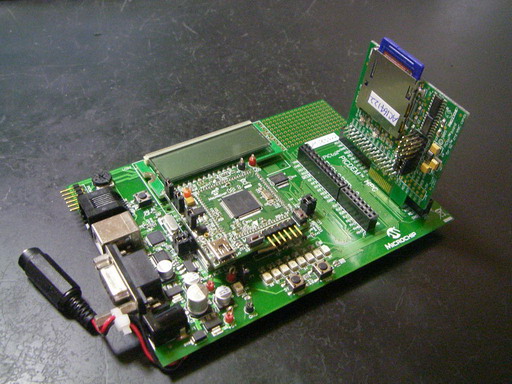
   <プログラム例>
//下記はmain()があるファイルmain.c の一部です。ダウンロードしたファイルに変更はコメント行も含め変更はしていません。


/********************************************************************
 FileName:              main.c
 Dependencies:  See INCLUDES section
 Processor:             PIC18, PIC24, and PIC32 USB Microcontrollers
 Hardware:              This demo is natively intended to be used on Microchip USB demo
                                boards supported by the MCHPFSUSB stack.  See release notes for
                                support matrix.  This demo can be modified for use on other hardware
                                platforms.
 Complier:      Microchip C18 (for PIC18), C30 (for PIC24), C32 (for PIC32)
 Company:               Microchip Technology, Inc.

 Software License Agreement:

 The software supplied herewith by Microchip Technology Incorporated
 (the 鼎ompany・ for its PICョ Microcontroller is intended and
 supplied to you, the Company痴 customer, for use solely and
 exclusively on Microchip PIC Microcontroller products. The
 software is owned by the Company and/or its supplier, and is
 protected under applicable copyright laws. All rights are reserved.
 Any use in violation of the foregoing restrictions may subject the
 user to criminal sanctions under applicable laws, as well as to
 civil liability for the breach of the terms and conditions of this
 license.

 THIS SOFTWARE IS PROVIDED IN AN 鄭S IS・CONDITION. NO WARRANTIES,
 WHETHER EXPRESS, IMPLIED OR STATUTORY, INCLUDING, BUT NOT LIMITED
 TO, IMPLIED WARRANTIES OF MERCHANTABILITY AND FITNESS FOR A
 PARTICULAR PURPOSE APPLY TO THIS SOFTWARE. THE COMPANY SHALL NOT,
 IN ANY CIRCUMSTANCES, BE LIABLE FOR SPECIAL, INCIDENTAL OR
 CONSEQUENTIAL DAMAGES, FOR ANY REASON WHATSOEVER.

********************************************************************
 File Description:

 Change History:
  Rev   Description
  ----  -----------------------------------------
  1.0   Initial release
  2.1   Updated for simplicity and to use common
                     coding style
********************************************************************/

/** INCLUDES *******************************************************/

#include "USB/USB.h"
#include "./USB/usb_function_msd.h"

#include "HardwareProfile.h"
#include "MDD File System\SD-SPI.h"

/** CONFIGURATION **************************************************/
#if defined(PICDEM_FS_USB)      // Configuration bits for PICDEM FS USB Demo Board (based on PIC18F4550)
        #pragma config PLLDIV   = 5         // (20 MHz crystal on PICDEM FS USB board)
        #pragma config CPUDIV   = OSC1_PLL2
        #pragma config USBDIV   = 2         // Clock source from 96MHz PLL/2
        #pragma config FOSC     = HSPLL_HS
        #pragma config FCMEN    = OFF
        #pragma config IESO     = OFF
        #pragma config PWRT     = OFF
        #pragma config BOR      = ON
        #pragma config BORV     = 3
        #pragma config VREGEN   = ON      //USB Voltage Regulator
        #pragma config WDT      = OFF
        #pragma config WDTPS    = 32768
        #pragma config MCLRE    = ON
        #pragma config LPT1OSC  = OFF
        #pragma config PBADEN   = OFF
//      #pragma config CCP2MX   = ON
        #pragma config STVREN   = ON
        #pragma config LVP      = OFF
//      #pragma config ICPRT    = OFF       // Dedicated In-Circuit Debug/Programming
        #pragma config XINST    = OFF       // Extended Instruction Set
        #pragma config CP0      = OFF
        #pragma config CP1      = OFF
//      #pragma config CP2      = OFF
//      #pragma config CP3      = OFF
        #pragma config CPB      = OFF
//      #pragma config CPD      = OFF
        #pragma config WRT0     = OFF
        #pragma config WRT1     = OFF
//      #pragma config WRT2     = OFF
//      #pragma config WRT3     = OFF
        #pragma config WRTB     = OFF       // Boot Block Write Protection
        #pragma config WRTC     = OFF
//      #pragma config WRTD     = OFF
        #pragma config EBTR0    = OFF
        #pragma config EBTR1    = OFF
//      #pragma config EBTR2    = OFF
//      #pragma config EBTR3    = OFF
        #pragma config EBTRB    = OFF


#elif defined(PIC18F87J50_PIM)                          // Configuration bits for PIC18F87J50 FS USB Plug-In Module board
        #pragma config XINST    = OFF           // Extended instruction set
        #pragma config STVREN   = ON            // Stack overflow reset
        #pragma config PLLDIV   = 3         // (12 MHz crystal used on this board)
        #pragma config WDTEN    = OFF           // Watch Dog Timer (WDT)
        #pragma config CP0      = OFF           // Code protect
        #pragma config CPUDIV   = OSC1      // OSC1 = divide by 1 mode
        #pragma config IESO     = OFF           // Internal External (clock) Switchover
        #pragma config FCMEN    = OFF           // Fail Safe Clock Monitor
        #pragma config FOSC     = HSPLL     // Firmware must also set OSCTUNE<PLLEN> to start PLL!
        #pragma config WDTPS    = 32768
//      #pragma config WAIT     = OFF           // Commented choices are
//      #pragma config BW       = 16            // only available on the
//      #pragma config MODE     = MM            // 80 pin devices in the
//      #pragma config EASHFT   = OFF           // family.
        #pragma config MSSPMSK  = MSK5
//      #pragma config PMPMX    = DEFAULT
//      #pragma config ECCPMX   = DEFAULT
        #pragma config CCP2MX   = DEFAULT

#elif defined(PIC18F46J50_PIM)
     #pragma config WDTEN = OFF          //WDT disabled (enabled by SWDTEN bit)
     #pragma config PLLDIV = 3           //Divide by 3 (12 MHz oscillator input)
     #pragma config STVREN = ON            //stack overflow/underflow reset enabled
     #pragma config XINST = OFF          //Extended instruction set disabled
     #pragma config CPUDIV = OSC1        //No CPU system clock divide
     #pragma config CP0 = OFF            //Program memory is not code-protected
     #pragma config OSC = HSPLL          //HS oscillator, PLL enabled, HSPLL used by USB
     #pragma config T1DIG = ON           //Sec Osc clock source may be selected
     #pragma config LPT1OSC = OFF        //high power Timer1 mode
     #pragma config FCMEN = OFF          //Fail-Safe Clock Monitor disabled
     #pragma config IESO = OFF           //Two-Speed Start-up disabled
     #pragma config WDTPS = 32768        //1:32768
     #pragma config DSWDTOSC = INTOSCREF //DSWDT uses INTOSC/INTRC as clock
     #pragma config RTCOSC = T1OSCREF    //RTCC uses T1OSC/T1CKI as clock
     #pragma config DSBOREN = OFF        //Zero-Power BOR disabled in Deep Sleep
     #pragma config DSWDTEN = OFF        //Disabled
     #pragma config DSWDTPS = 8192       //1:8,192 (8.5 seconds)
     #pragma config IOL1WAY = OFF        //IOLOCK bit can be set and cleared
     #pragma config MSSP7B_EN = MSK7     //7 Bit address masking
     #pragma config WPFP = PAGE_1        //Write Protect Program Flash Page 0
     #pragma config WPEND = PAGE_0       //Start protection at page 0
     #pragma config WPCFG = OFF          //Write/Erase last page protect Disabled
     #pragma config WPDIS = OFF          //WPFP[5:0], WPEND, and WPCFG bits ignored
#elif defined(LOW_PIN_COUNT_USB_DEVELOPMENT_KIT)
        //14K50
        #pragma config CPUDIV = NOCLKDIV
        #pragma config USBDIV = OFF
        #pragma config FOSC   = HS
        #pragma config PLLEN  = ON
        #pragma config FCMEN  = OFF
        #pragma config IESO   = OFF
        #pragma config PWRTEN = OFF
        #pragma config BOREN  = OFF
        #pragma config BORV   = 30
//        #pragma config VREGEN = ON
        #pragma config WDTEN  = OFF
        #pragma config WDTPS  = 32768
        #pragma config MCLRE  = OFF
        #pragma config HFOFST = OFF
        #pragma config STVREN = ON
        #pragma config LVP    = OFF
        #pragma config XINST  = OFF
        #pragma config BBSIZ  = OFF
        #pragma config CP0    = OFF
        #pragma config CP1    = OFF
        #pragma config CPB    = OFF
        #pragma config WRT0   = OFF
        #pragma config WRT1   = OFF
        #pragma config WRTB   = OFF
        #pragma config WRTC   = OFF
        #pragma config EBTR0  = OFF
        #pragma config EBTR1  = OFF
        #pragma config EBTRB  = OFF

#elif defined(EXPLORER_16)
    #if defined(__PIC24FJ256GB110__) || defined(__PIC24FJ256GB210__)
        _CONFIG1( JTAGEN_OFF & GCP_OFF & GWRP_OFF & FWDTEN_OFF & ICS_PGx2)
        _CONFIG2( 0xF7FF & IESO_OFF & FCKSM_CSDCMD & OSCIOFNC_ON & POSCMOD_HS & FNOSC_PRIPLL & PLLDIV_DIV2 & IOL1WAY_ON)
    #elif defined(__PIC24FJ64GB004__)
        _CONFIG1(WDTPS_PS1 & FWPSA_PR32 & WINDIS_OFF & FWDTEN_OFF & ICS_PGx1 & GWRP_OFF & GCP_OFF & JTAGEN_OFF)
        _CONFIG2(POSCMOD_HS & I2C1SEL_PRI & IOL1WAY_OFF & OSCIOFNC_ON & FCKSM_CSDCMD & FNOSC_PRIPLL & PLL96MHZ_ON & PLLDIV_DIV2 & IESO_ON)
        _CONFIG3(WPFP_WPFP0 & SOSCSEL_SOSC & WUTSEL_LEG & WPDIS_WPDIS & WPCFG_WPCFGDIS & WPEND_WPENDMEM)
        _CONFIG4(DSWDTPS_DSWDTPS3 & DSWDTOSC_LPRC & RTCOSC_SOSC & DSBOREN_OFF & DSWDTEN_OFF)
    #elif defined(__32MX460F512L__)
        #pragma config UPLLEN   = ON        // USB PLL Enabled
        #pragma config FPLLMUL  = MUL_15        // PLL Multiplier
        #pragma config UPLLIDIV = DIV_2         // USB PLL Input Divider
        #pragma config FPLLIDIV = DIV_2         // PLL Input Divider
        #pragma config FPLLODIV = DIV_1         // PLL Output Divider
        #pragma config FPBDIV   = DIV_1         // Peripheral Clock divisor
        #pragma config FWDTEN   = OFF           // Watchdog Timer
        #pragma config WDTPS    = PS1           // Watchdog Timer Postscale
        #pragma config FCKSM    = CSDCMD        // Clock Switching & Fail Safe Clock Monitor
        #pragma config OSCIOFNC = OFF           // CLKO Enable
        #pragma config POSCMOD  = HS            // Primary Oscillator
        #pragma config IESO     = OFF           // Internal/External Switch-over
        #pragma config FSOSCEN  = OFF           // Secondary Oscillator Enable (KLO was off)
        #pragma config FNOSC    = PRIPLL        // Oscillator Selection
        #pragma config CP       = OFF           // Code Protect
        #pragma config BWP      = OFF           // Boot Flash Write Protect
        #pragma config PWP      = OFF           // Program Flash Write Protect
        #pragma config ICESEL   = ICS_PGx2      // ICE/ICD Comm Channel Select
        #pragma config DEBUG    = ON            // Background Debugger Enable
     #elif defined(__32MX795F512L__)
        #pragma config UPLLEN   = ON        // USB PLL Enabled
        #pragma config FPLLMUL  = MUL_15        // PLL Multiplier
        #pragma config UPLLIDIV = DIV_2         // USB PLL Input Divider
        #pragma config FPLLIDIV = DIV_2         // PLL Input Divider
        #pragma config FPLLODIV = DIV_1         // PLL Output Divider
        #pragma config FPBDIV   = DIV_1         // Peripheral Clock divisor
        #pragma config FWDTEN   = OFF           // Watchdog Timer
        #pragma config WDTPS    = PS1           // Watchdog Timer Postscale
        #pragma config FCKSM    = CSDCMD        // Clock Switching & Fail Safe Clock Monitor
        #pragma config OSCIOFNC = OFF           // CLKO Enable
        #pragma config POSCMOD  = HS            // Primary Oscillator
        #pragma config IESO     = OFF           // Internal/External Switch-over
        #pragma config FSOSCEN  = OFF           // Secondary Oscillator Enable (KLO was off)
        #pragma config FNOSC    = PRIPLL        // Oscillator Selection
        #pragma config CP       = OFF           // Code Protect
        #pragma config BWP      = OFF           // Boot Flash Write Protect
        #pragma config PWP      = OFF           // Program Flash Write Protect
        #pragma config ICESEL   = ICS_PGx2      // ICE/ICD Comm Channel Select
        #pragma config DEBUG    = ON            // Background Debugger Enable
    #else
        #error No hardware board defined, see "HardwareProfile.h" and __FILE__
    #endif
#elif defined(PIC24F_STARTER_KIT)
    _CONFIG1( JTAGEN_OFF & GCP_OFF & GWRP_OFF & COE_OFF & FWDTEN_OFF & ICS_PGx2)
    _CONFIG2( 0xF7FF & IESO_OFF & FCKSM_CSDCMD & OSCIOFNC_OFF & POSCMOD_HS & FNOSC_PRIPLL & PLLDIV_DIV3 & IOL1WAY_ON)
#elif defined(PIC24FJ256DA210_DEV_BOARD)
    _CONFIG1(FWDTEN_OFF & ICS_PGx2 & GWRP_OFF & GCP_OFF & JTAGEN_OFF)
    _CONFIG2(POSCMOD_HS & IOL1WAY_ON & OSCIOFNC_ON & FCKSM_CSDCMD & FNOSC_PRIPLL & PLL96MHZ_ON & PLLDIV_DIV2 & IESO_OFF)
#else
    #error No hardware board defined, see "HardwareProfile.h" and __FILE__
#endif


/** VARIABLES ******************************************************/
#pragma udata

#if defined(__C30__) || defined(__C32__)
//The LUN variable definition is critical to the MSD function driver.  This
//  array is a structure of function pointers that are the functions that
//  will take care of each of the physical media.  For each additional LUN
//  that is added to the system, an entry into this array needs to be added
//  so that the stack can know where to find the physical layer functions.
//  In this example the media initialization function is named
//  "MediaInitialize", the read capacity function is named "ReadCapacity",
//  etc.
LUN_FUNCTIONS LUN[MAX_LUN + 1] =
{
    {
        &MDD_SDSPI_MediaInitialize,
        &MDD_SDSPI_ReadCapacity,
        &MDD_SDSPI_ReadSectorSize,
        &MDD_SDSPI_MediaDetect,
        &MDD_SDSPI_SectorRead,
        &MDD_SDSPI_WriteProtectState,
        &MDD_SDSPI_SectorWrite
    }
};
#endif

/* Standard Response to INQUIRY command stored in ROM   */
const ROM InquiryResponse inq_resp = {
        0x00,           // peripheral device is connected, direct access block device
        0x80,           // removable
        0x04,           // version = 00=> does not conform to any standard, 4=> SPC-2
        0x02,           // response is in format specified by SPC-2
        0x20,           // n-4 = 36-4=32= 0x20
        0x00,           // sccs etc.
        0x00,           // bque=1 and cmdque=0,indicates simple queueing 00 is obsolete,
                        // but as in case of other device, we are just using 00
        0x00,           // 00 obsolete, 0x80 for basic task queueing
        {'M','i','c','r','o','c','h','p'
    },
        // this is the T10 assigned Vendor ID
        {'M','a','s','s',' ','S','t','o','r','a','g','e',' ',' ',' ',' '
    },
        {'0','0','0','1'
    }
};

/** PRIVATE PROTOTYPES *********************************************/
static void InitializeSystem(void);
void USBDeviceTasks(void);
void ProcessIO(void);
void YourHighPriorityISRCode(void);
void YourLowPriorityISRCode(void);

/** VECTOR REMAPPING ***********************************************/
#if defined(__18CXX)
        //On PIC18 devices, addresses 0x00, 0x08, and 0x18 are used for
        //the reset, high priority interrupt, and low priority interrupt
        //vectors.  However, the current Microchip USB bootloader
        //examples are intended to occupy addresses 0x00-0x7FF or
        //0x00-0xFFF depending on which bootloader is used.  Therefore,
        //the bootloader code remaps these vectors to new locations
        //as indicated below.  This remapping is only necessary if you
        //wish to program the hex file generated from this project with
        //the USB bootloader.  If no bootloader is used, edit the
        //usb_config.h file and comment out the following defines:
        //#define PROGRAMMABLE_WITH_USB_HID_BOOTLOADER
        //#define PROGRAMMABLE_WITH_USB_LEGACY_CUSTOM_CLASS_BOOTLOADER

        #if defined(PROGRAMMABLE_WITH_USB_HID_BOOTLOADER)
                #define REMAPPED_RESET_VECTOR_ADDRESS                   0x1000
                #define REMAPPED_HIGH_INTERRUPT_VECTOR_ADDRESS  0x1008
                #define REMAPPED_LOW_INTERRUPT_VECTOR_ADDRESS   0x1018
        #elif defined(PROGRAMMABLE_WITH_USB_MCHPUSB_BOOTLOADER)
                #define REMAPPED_RESET_VECTOR_ADDRESS                   0x800
                #define REMAPPED_HIGH_INTERRUPT_VECTOR_ADDRESS  0x808
                #define REMAPPED_LOW_INTERRUPT_VECTOR_ADDRESS   0x818
        #else
                #define REMAPPED_RESET_VECTOR_ADDRESS                   0x00
                #define REMAPPED_HIGH_INTERRUPT_VECTOR_ADDRESS  0x08
                #define REMAPPED_LOW_INTERRUPT_VECTOR_ADDRESS   0x18
        #endif

        #if defined(PROGRAMMABLE_WITH_USB_HID_BOOTLOADER)||defined(PROGRAMMABLE_WITH_USB_MCHPUSB_BOOTLOADER)
        extern void _startup (void);        // See c018i.c in your C18 compiler dir
        #pragma code REMAPPED_RESET_VECTOR = REMAPPED_RESET_VECTOR_ADDRESS
        void _reset (void)
        {
            _asm goto _startup _endasm
        }
        #endif
        #pragma code REMAPPED_HIGH_INTERRUPT_VECTOR = REMAPPED_HIGH_INTERRUPT_VECTOR_ADDRESS
        void Remapped_High_ISR (void)
        {
             _asm goto YourHighPriorityISRCode _endasm
        }
        #pragma code REMAPPED_LOW_INTERRUPT_VECTOR = REMAPPED_LOW_INTERRUPT_VECTOR_ADDRESS
        void Remapped_Low_ISR (void)
        {
             _asm goto YourLowPriorityISRCode _endasm
        }

        #if defined(PROGRAMMABLE_WITH_USB_HID_BOOTLOADER)||defined(PROGRAMMABLE_WITH_USB_MCHPUSB_BOOTLOADER)
        //Note: If this project is built while one of the bootloaders has
        //been defined, but then the output hex file is not programmed with
        //the bootloader, addresses 0x08 and 0x18 would end up programmed with 0xFFFF.
        //As a result, if an actual interrupt was enabled and occured, the PC would jump
        //to 0x08 (or 0x18) and would begin executing "0xFFFF" (unprogrammed space).  This
        //executes as nop instructions, but the PC would eventually reach the REMAPPED_RESET_VECTOR_ADDRESS
        //(0x1000 or 0x800, depending upon bootloader), and would execute the "goto _startup".  This
        //would effective reset the application.

        //To fix this situation, we should always deliberately place a
        //"goto REMAPPED_HIGH_INTERRUPT_VECTOR_ADDRESS" at address 0x08, and a
        //"goto REMAPPED_LOW_INTERRUPT_VECTOR_ADDRESS" at address 0x18.  When the output
        //hex file of this project is programmed with the bootloader, these sections do not
        //get bootloaded (as they overlap the bootloader space).  If the output hex file is not
        //programmed using the bootloader, then the below goto instructions do get programmed,
        //and the hex file still works like normal.  The below section is only required to fix this
        //scenario.
        #pragma code HIGH_INTERRUPT_VECTOR = 0x08
        void High_ISR (void)
        {
             _asm goto REMAPPED_HIGH_INTERRUPT_VECTOR_ADDRESS _endasm
        }
        #pragma code LOW_INTERRUPT_VECTOR = 0x18
        void Low_ISR (void)
        {
             _asm goto REMAPPED_LOW_INTERRUPT_VECTOR_ADDRESS _endasm
        }
        #endif  //end of "#if defined(PROGRAMMABLE_WITH_USB_HID_BOOTLOADER)||defined(PROGRAMMABLE_WITH_USB_LEGACY_CUSTOM_CLASS_BOOTLOADER)"

        #pragma code


        //These are your actual interrupt handling routines.
        #pragma interrupt YourHighPriorityISRCode
        void YourHighPriorityISRCode()
        {
                //Check which interrupt flag caused the interrupt.
                //Service the interrupt
                //Clear the interrupt flag
                //Etc.
        #if defined(USB_INTERRUPT)
                USBDeviceTasks();
        #endif

        }       //This return will be a "retfie fast", since this is in a #pragma interrupt section
        #pragma interruptlow YourLowPriorityISRCode
        void YourLowPriorityISRCode()
        {
                //Check which interrupt flag caused the interrupt.
                //Service the interrupt
                //Clear the interrupt flag
                //Etc.

        }       //This return will be a "retfie", since this is in a #pragma interruptlow section

#elif defined(__C30__)
    #if defined(PROGRAMMABLE_WITH_USB_HID_BOOTLOADER)
        /*
         *      ISR JUMP TABLE
         *
         *      It is necessary to define jump table as a function because C30 will
         *      not store 24-bit wide values in program memory as variables.
         *
         *      This function should be stored at an address where the goto instructions
         *      line up with the remapped vectors from the bootloader's linker script.
         *
         *  For more information about how to remap the interrupt vectors,
         *  please refer to AN1157.  An example is provided below for the T2
         *  interrupt with a bootloader ending at address 0x1400
         */
//        void __attribute__ ((address(0x1404))) ISRTable(){
//
//              asm("reset"); //reset instruction to prevent runaway code
//              asm("goto %0"::"i"(&_T2Interrupt));  //T2Interrupt's address
//        }
    #endif
#endif


/** DECLARATIONS ***************************************************/
#pragma code

/********************************************************************
 * Function:        void main(void)
 *
 * PreCondition:    None
 *
 * Input:           None
 *
 * Output:          None
 *
 * Side Effects:    None
 *
 * Overview:        Main program entry point.
 *
 * Note:            None
 *******************************************************************/
#if defined(__18CXX)
void main(void)
#else
int main(void)
#endif
{
    InitializeSystem();

    #if defined(USB_INTERRUPT)
        USBDeviceAttach();
    #endif

    while(1)
    {
        #if defined(USB_POLLING)
                // Check bus status and service USB interrupts.
        USBDeviceTasks(); // Interrupt or polling method.  If using polling, must call
                                          // this function periodically.  This function will take care
                                          // of processing and responding to SETUP transactions
                                          // (such as during the enumeration process when you first
                                          // plug in).  USB hosts require that USB devices should accept
                                          // and process SETUP packets in a timely fashion.  Therefore,
                                          // when using polling, this function should be called
                                          // frequently (such as once about every 100 microseconds) at any
                                          // time that a SETUP packet might reasonably be expected to
                                          // be sent by the host to your device.  In most cases, the
                                          // USBDeviceTasks() function does not take very long to
                                          // execute (~50 instruction cycles) before it returns.
        #endif


                // Application-specific tasks.
                // Application related code may be added here, or in the ProcessIO() function.
        ProcessIO();
    }//end while
}//end main


//以下省略
////必要なファイル、マニュアル等はすべて マイクロチップUSBサイト  及び Microchip Applications Libraryにあります。
<動作結果>
| モード | PCの画面 |
|
| ① | USBプラグを試作品に挿入 → PCが試作品を認識 |
|
| ② | エクスプローラで SDカードの内容を表示 |
|
| ③ | 音声ファイルのWAVファイルを メディアプレーヤーで実行 → PCに接続されたスピーカより 連続的なスムーズな音(音楽)が発生 |
|
動画ファイルのWMVファイルを メディアプレーヤで実行 → 連続的なスムーズなQVGAの動画を再生 |
|
<追記>
★ PCがターゲットボードを認識しなくなった場合、PCのUSBポートを変更すると認識するようになることがあります。
★ PICのソフトに問題がある場合PCが不調になる可能性があります。復元ポイントを設定後実験に着手することをおすすめします。Windowsは
正常モードからたち上がらなくなった場合、セーフモードから復元ポイントに戻すこともできます。
![]()
![]()