■ モメンタリースイッチによるLED ON/OFF 

モメンタリースイッチとはPCのキーボードのキースイッチのように押しているときだけON(正確にはOFFも含めて動作)
するスイッチのことです。このスイッチをつかってLEDをON/OFFするにはチャタリングがあるので若干工夫が必要です。
ソフトはどのようにこのチャタリングによる誤動作を防止するかでいろいろな方法があります。大きくわけて以下の4つが
あります。
(1) 割込みを使いわないでスイッチ信号を検出する方法 <CCS編> <C18編>
(2) タイマ割込みを使ってスイッチ信号を検出する方法 <CCS編> <C18編>
(3) ポートBのbit0からの外部割込みポートを使ってスイッチ信号を検出する方法 <CCS編> <C18編>
(4) ポートBのbit4〜bit7のポート変化割り込みを使ってスイッチ信号を検出する方法 <CCS編> <C18編>
尚、高い信頼性の回路にする場合はソフトのフィルタだけではなく、スイッチ回路にハードのフィルタも挿入します。
<試作品仕様>
① 電源を投入した時はLEDは消灯していこと。
② LEDが消灯している状態で、モメンタリースイッチを押すとLEDが点灯
すること。 スイッチから指を離してもLEDは点灯し続けること。
③ LEDが点灯している状態で、モメンタリースチッチを押すとLEDが消灯
すること。 スイッチから指を離してもLEDは消灯し続けること。
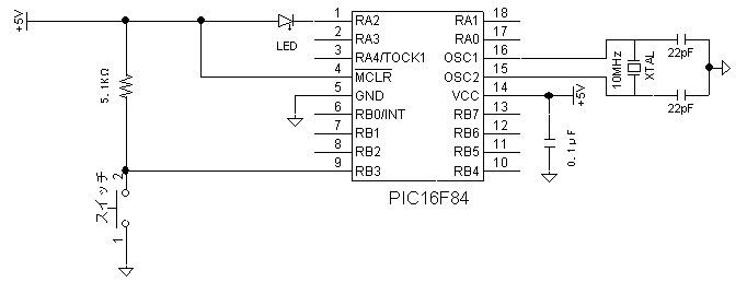
(1)割込みを使いわないでスイッチ信号を検出方法
<CCS編> ********************************************************************************
モメンタリスイッチによるLEDの ON/OFF **********************************************************
<試作品回路図> スイッチ回路にフィルタがない場合 (→ 回路図のPDFファイル)
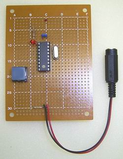
<試作品外観>
<試作品回路図> スイッチ回路にフィルタを入れた場合 (→回路図のPDFファイル)

 <プログラム例><CCS編> 割込みを使わない方法

#include <16f84a.h>
#use delay(clock=10000000)
#FUSES  HS,NOWDT,NOPROTECT,PUT
short int detect = 0,     //RBポート検出: RB3が”0”の状態を検出すると”1”、押されていない状態を検出すると”0”となる
          SwMode = 0,     //スイッチ押され検出: スイッチが押されたと判断した場合”1”、押されていないと判断している場合”0”となる
          Led = 0;        //LEDモード  LEDが点灯の場合”1”、消灯の場合”0”


main(){
        Led = 0;                //LEDのモードを消灯モードにセットして
        output_high(PIN_A2);    //RA2ポートをHigh(5v)にしてLEDを消灯する

        while(1)
        {
                if(SwMode == 0)                               //スイッチが押されていないと判断している場合
                {
                        if(input(PIN_B3) == 0)detect = 1;     //RB3ポートをチェックして”0”なら
                                                                                        // スイッチが押されたようだがノイズやチャタリングの可能性もあるので

                        delay_ms(100);                                  //100msec後に

                        if((input(PIN_B3) == 0)  && (detect == 1)) {    // RB3ポートをもう一度チェックして 再度”0”なら
                                SwMode = 1;                                             //スイッチが押されたと判断する
                                if(Led == 1)                             // LEDが点灯していたのなら
                                {
                                        Led = 0;                         //LEDのモードを消灯モードにセットして
                                        output_high(PIN_A2);             //RA2ポートをHigh(5v)にしてLEDを消灯する
                                }
                                else                                      // またLEDが消灯していたなら
                                {
                                        Led = 1;                          // LEDのモードを点灯モードにセットして
                                        output_low(PIN_A2);               // RA2ポートをLow(0v)にしてLEDを点灯する
                                }
                        }
                }
                if(input(PIN_B3) == 1)SwMode = 0;       //RB3ポートが”0”(スイッチが一瞬でも離れた) なら、スイッチ検出を開始
        }

        return 0;
}
<HI-TECH編> モメンタリスイッチによるLED OM/OFF
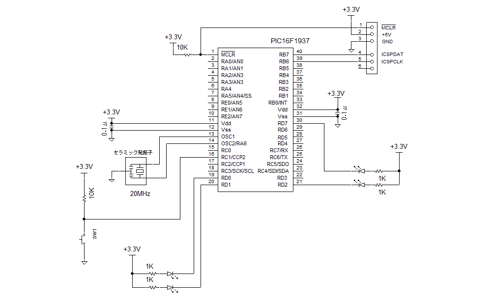
<試作品回路図> (→回路図のPDFファイル)
PIC16F1937を使用した例を以下に示します
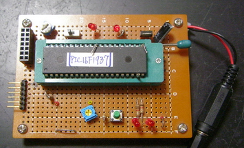
<試作品外観>下記の写真には上記回路図にはない、また本テーマと関係のない部品が多々写っています
 <プログラム例>

//HI-TEC LED  Momentary SW ON_OFF       (割り込みなし)


//Delay style    Time 2sec: On Time 1sec,Off Time 1sec
//                                                PIC16F1937

#include  <htc.h>

#define _XTAL_FREQ 20000000             //Ceramic :20MHz

//Configuration
__CONFIG(
                FOSC_HS &                       // EXTRC Oscillator, RC on RA7/OSC1/CLKIN
                WDTE_OFF &              // Power-up Timer Enable bit// PWRT disabled
                PWRTE_ON &              // MCLR Pin Function Select// RE3/MCLR/VPP pin function is MCLR
                MCLRE_ON &              // RE3/MCLR/VPP pin function is digital input
                CP_OFF  &               // Program memory code protection is enabled
                CPD_OFF &               // Data memory code protection is enabled
                BOREN_OFF &             // Clock Out Enable bit// CLKOUT function is disabled. I/O or oscillator function on RA6/CLKOUT
                CLKOUTEN_OFF &  // CLKOUT function is enabled on RA6/CLKOUT pin
                IESO_OFF &              // Fail Clock Monitor Enable// Fail-Safe Clock Monitor is enabled
                FCMEN_ON                // Fail-Safe Clock Monitor is disabled
                );


__CONFIG(
                WRT_OFF &       // 000h to 1FFh write protected, 200h to 1FFFh may be modified by EECON control
                PLLEN_OFF &     // 4x PLL disabled
                STVREN_OFF &// Brown-out Reset Voltage selection// Brown-out Reset Voltage (VBOR) set to 1.9 V
                BORV_19 &       // Brown-out Reset Voltage (VBOR) set to 2.7 V
//              DEBUG_OFF &     // Background debugger is enabled
                LVP_OFF         // HV on MCLR/VPP must not be used for programming
                );

short int detect = 0,     //RBポート検出: RB3が”0”の状態を検出すると”1”、押されていない状態を検出すると”0”となる
          SwMode = 0,     //スイッチ押され検出: スイッチが押されたと判断した場合”1”、押されていないと判断している場合”0”となる
          Led = 0;        //LEDモード  LEDが点灯の場合”1”、消灯の場合”0”


int main()
{

        TRISD = 0;      //D port: outport
        TRISC = 0xFF;           // C port inport

        Led = 0;             //LEDのモードを消灯モードにセットして
        LATD0 = 1;                      //RD0 port LED off
        LATD1 = 1;                      //RD1 port LED off
        LATD2 = 1;                      //RD2 port LED off
        LATD7 = 1;                      //RD7 port LED off
        while(1)
        {
        if(SwMode == 0)                               //スイッチが押されていないと判断している場合
        {
                if(PORTCbits.RC1 == 0)detect = 1;       ///RB3ポートをチェックして”0”なら
                                            // スイッチが押されたようだがノイズやチャタリングの可能性もあるので
                        __delay_ms(100);                                  //100msec後に

                        if((PORTCbits.RC1 == 0) && (detect == 1))       //ポートをもう一度チェックして 再度”0”なら
            {                                                                                                                                                                                                                   SwMode = 1;                                             //スイッチが押されたと判断する
                                if(Led == 1)                             // LEDが点灯していたのなら
                                {
                                        Led = 0;           //LEDのモードを消灯モードにセットして  ポートをHigh(5v)にしてLEDを消灯する
                                        LATD0 = 1;                      //RD0 port LED off
                                        LATD1 = 1;                      //RD1 port LED off
                                        LATD2 = 1;                      //RD2 port LED off
                                        LATD7 = 1;                      //RD7 port LED off
                                }
                                else            // またLEDが消灯していたなら
                                {
                                        Led = 1;
                                        LATD0 = 0;                      //RD0 port LED on
                                        LATD1 = 0;                      //RD1 port LED on
                                        LATD2 = 0;                      //RD2 port LED on
                                        LATD7 = 0;                      //RD7 port LED on
                                }
                        }
                }
                if(PORTCbits.RC1 == 1)SwMode = 0;       //RB3ポートが”0”(スイッチが一瞬でも離れた) なら、スイッチ検出を開始
        }

        return 0;
}
<C18編> *************************************************************************************:
モメンタリスイッチによるLEDのON/OFF *************************************************************
割込みをつかいわない方法
<試作品回路図> (→回路図のPDFファイル)
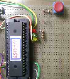
PIC18F4550を使用した例を以下に示します
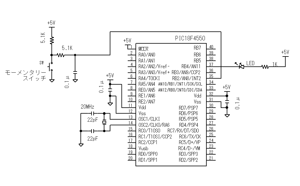
<試作品外観>下記の写真には上記回路図にはない、また本テーマと関係のない部品が多々写っています
 <プログラム例><C18編> 割込みを使わない方法

/*
モーメンタリスイッチによるLED ON/OFF
        遅延関数による方法(割込みを使わない方法)
*/

#include <p18f4550.h>
#include <stdio.h>
#include <delays.h>

#pragma config PLLDIV = 5          //96MHz PLL Prescalar(1、2、3、4、5、6、10、12のみ) : 外部周波数÷4MHz
                                   //20MHz ÷ 5 = 4MHz → 96MHz(=4MHz×24 :固定)
#pragma config USBDIV = 2          // Full Speed USB Clock Source Selection : 2(constant)
#pragma config CPUDIV = OSC1_PLL2  //CPU System Clock Postscaler
                                                                        // PICのシステムクロック周波数:48MHz(=96MHz ÷2)
#pragma config FOSC = HS           // システムクロック=20MHz
//#pragma config FOSC = HSPLL_HS   // システムクロック=48MHz

#pragma config WDT = OFF           //ウォッチドックタイマOFF
#pragma config LVP = OFF           //低電圧書き込みOFF
#pragma config PWRT = ON           //パワーアップタイマON
#pragma config BOR = ON            //ブラウンアウトリセットON(ハードウェアのみ)
#pragma config BORV = 1            //Brown out Voltage = 4.33v
                                   // ref: BORV=0 → 4.59v    BORV=2 → 2.79v  BORV=4 → 2.05v
#pragma config PBADEN = OFF        //リセットでポートBの全アナログポートをデジタルI/Oにリセット
                                   // PORTB A/D Enable bit = 0 (CONFIG3H)


int detect = 0,                    //RBポート検出: RB2が”0”の状態を検出すると”1”、押されていない状態を検出すると”0”となる
        SwMode = 0,                //スイッチ押され検出: スイッチが押されたと判断した場合”1”、押されていないと判断している場合”0”となる
        Led = 0;                   //LEDモード  LEDが点灯の場合”1”、消灯の場合”0”


void delay_ms (long int cycle)     // CCSコンパイラと同じ delay_ms(long int) 関数を設計
{
     long int i = 0;
     for (i = 0; i < cycle; i++)Delay1KTCYx(5);     // 0.05μsec × 4 × 5000 = 1msec システムクロック=20Mhz
}

void main (void)
{
        TRISB = 0b00000100;     // B port: RB2:in その他:out
        Led = 0;                //LEDのモードを消灯モードにセットして
        LATBbits.LATB4 = 1 ;    //RB4ポートをHigh(5v)にしてLEDを消灯する

        while(1)
        {
                if(SwMode == 0)                              //スイッチが押されていないと判断している場合
                {
                        if( PORTBbits.RB2 == 0)detect = 1;   //RB2ポートをチェックして”0”なら
                                                             // スイッチが押されたようだがノイズやチャタリングの可能性もあるので
                                delay_ms(100);               //100msec後に

                                if((PORTBbits.RB2 == 0)  && (detect == 1))  //RB2ポートをもう一度チェックして 再度”0”なら
                                {
                                        SwMode = 1;                          //スイッチが押されたと判断する
                                        if(Led == 1)                         //LEDが点灯していたのなら
                                        {
                                                Led = 0;                     //LEDのモードを消灯モードにセットして
                                                LATBbits.LATB4 = 1;          //RB4ポートをHigh(5v)にしてLEDを消灯する
                                        }
                                        else                                 // またLEDが消灯していたなら
                                        {
                                                Led = 1;                     // LEDのモードを点灯モードにセットして
                                                LATBbits.LATB4 = 0;          // RA4ポートをLow(0v)にしてLEDを点灯する
                                        }
                                }
                }
                if( PORTBbits.RB2 == 1)SwMode = 0;                           //RB2ポートが”0”(スイッチが一瞬でも離れた) なら、スイッチ検出を開始
        }
}
(2) タイマ割込みを使ってスイッチ信号を検出する方法
<CCS編> ************************************************************************************
モメンタリスイッチによるLEDのON/OFF *************************************************************
<試作品回路図>スイッチ回路にフィルタがない場合 (→ 回路図のPDFファイル)
 <プログラム例><CCS編> タイマ割込みを使った方法

//------------------------------------------------------------------------------------------
#include <16F84a.h>
#use delay(clock=10000000)
#FUSES  HS,NOWDT,NOPROTECT,PUT
short int Led= 0;       //LEDモード : LEDが点灯の場合”1”、消灯の場合”0”
int swCount = 0;        //10msec毎にRB3ポートがチェックされ”0”なら加算されてる


#int_rtcc
void interval(){                            //10msec毎にタイマ割込みが発生しこの関数が実行される
        set_rtcc(157);                      //(255-98)=157  rtcc=98  0.1usec*4*256*98=10035usec = 10.035msec

        if(input(PIN_B3) == 0)swCount++;     //10msec毎にRB3ポートがチェックされ”0”なら加算されてる
        else swCount = 0;                    //RB3が”0”でないならswCountはリセットされる

        if(swCount == 8)                     //8回連続でRB3が”0”の場合
        {
                        if(Led == 0)         //LEDが消灯していたなら
                {
                        Led = 1;              //LED点灯モードにセットして
                        output_low(PIN_A2);   // RA2ポートをLowにしてLEDを点灯する
                }
                else                          //LEDが点灯していたなら
                {
                        Led = 0;              //LEDを消灯モードにセットして
                        output_high(PIN_A2);  //RA2ポートをhighにしてLEDを消灯する
                }
        }
        if(swCount >= 10)swCount = 9;         //スイッチが押されつづけられた場合はLEDの点灯、消灯は繰り返さない

}


main(){
        setup_counters(RTCC_INTERNAL,RTCC_DIV_256);     //タイマ0のプリスケーらは1/256にセット
        set_rtcc(157);                                  //タイマ0のカウンタは157をセット
        enable_interrupts(INT_RTCC);                    //タイマ0の割込みを許可
        enable_interrupts(GLOBAL);                      // すべての割り込みを許可

        Led = 0;
        output_high(PIN_A2);                            //電源投入でLED消灯

        while(1){                                      //割込みが発生する以外は何もしないで待つ
        }

        return 0;
}
<HI-TEC編> 割り込みタイマによるモメンタリスイッチ検出
<試作品回路図> (→回路図のPDFファイル)
PIC16F1937を使用した例を以下に示します
<試作品外観>下記の写真には上記回路図にはない、また本テーマと関係のない部品が多々写っています
//HI-TEC LED  Momentary SW ON_OFF       (割り込み有)
//  10msec毎のタイマ割り込みによるSW検出                                     PIC16F1937

#include  <htc.h>


#define _XTAL_FREQ 20000000             //Ceramic :20MHz

//Configuration
__CONFIG(
                FOSC_HS &                       // EXTRC Oscillator, RC on RA7/OSC1/CLKIN
                WDTE_OFF &              // Power-up Timer Enable bit// PWRT disabled
                PWRTE_ON &              // MCLR Pin Function Select// RE3/MCLR/VPP pin function is MCLR
                MCLRE_ON &              // RE3/MCLR/VPP pin function is digital input
                CP_OFF  &               // Program memory code protection is enabled
                CPD_OFF &               // Data memory code protection is enabled
                BOREN_OFF &             // Clock Out Enable bit// CLKOUT function is disabled. I/O or oscillator function on RA6/CLKOUT
                CLKOUTEN_OFF &  // CLKOUT function is enabled on RA6/CLKOUT pin
                IESO_OFF &              // Fail Clock Monitor Enable// Fail-Safe Clock Monitor is enabled
                FCMEN_ON                // Fail-Safe Clock Monitor is disabled
                );


__CONFIG(
                WRT_OFF &       // 000h to 1FFh write protected, 200h to 1FFFh may be modified by EECON control
                PLLEN_OFF &     // 4x PLL disabled
                STVREN_OFF &// Brown-out Reset Voltage selection// Brown-out Reset Voltage (VBOR) set to 1.9 V
                BORV_19 &       // Brown-out Reset Voltage (VBOR) set to 2.7 V
//              DEBUG_OFF &     // Background debugger is enabled
                LVP_OFF         // HV on MCLR/VPP must not be used for programming
                );


short int Led = 0;       //LEDモード : LEDが点灯の場合”1”、消灯の場合”0”
int swCount = 0;        //10msec毎にRB3ポートがチェックされ”0”なら加算されてる


void interrupt T1Handler(void)  //10msec毎の割り込み
{
        TMR1IF = 0;     //フラグクリア

//アップカウンタの値設定
//Clock: 20MHz/4 → 5MHz 0.2μsec
// 10msec毎の割り込みを行う
//プリスケーラ 1/8 //Prescale Select bits

//    (65536 -N)*0.2*8 = 10000
//     N = 65536 - 10000 /8/0.2  = 59286
//     59268/256 = 231
//     59286 -256*231 = 150
//     59286 ÷ 256 = 231 余り150
        TMR1H = 231;                            //
        TMR1L = 150;


        if(PORTCbits.RC1 == 0)swCount++;        ///RB3ポートをチェックして”0”なら
        else swCount = 0;                    //RB3が”0”でないならswCountはリセットされる

        if(swCount == 8)                     //8回連続でRB3が”0”の場合
        {
                if(Led == 0)         //LEDが消灯していたなら
                {
                        Led = 1;              //LED点灯モードにセットして  // 各ポートをLowにしてLEDを点灯する
                        LATD0 = 0;                      //RD0 port LED off
                        LATD1 = 0;                      //RD1 port LED off
                        LATD2 = 0;                      //RD2 port LED off
                        LATD7 = 0;                      //RD7 port LED off

                }
                else                          //LEDが点灯していたなら
                {
                        Led = 0;              //LEDを消灯モードにセットして
                        LATD0 = 1;                      //RD0 port LED off
                        LATD1 = 1;                      //RD1 port LED off
                        LATD2 = 1;                      //RD2 port LED off
                        LATD7 = 1;                      //RD7 port LED off
                }
        }
        if(swCount >= 10)swCount = 9;         //スイッチが押されつづけられた場合はLEDの点灯、消灯は繰り返さない
}


int main()
{

        TRISD = 0;      //D port: outport
        TRISC = 0xFF;           // C port inport

        Led = 0;             //LEDのモードを消灯モードにセットして
        LATD0 = 1;                      //RD0 port LED off
        LATD1 = 1;                      //RD1 port LED off
        LATD2 = 1;                      //RD2 port LED off
        LATD7 = 1;                      //RD7 port LED off


//T1CON レジスタ(Timer1 Control Resister)
        TMR1CS1 = 0;    //Timer1 clock source: Fosc/4 //Timer1 Clock Source Select bits
        TMR1CS0 = 0;    //TMR1CS<1:0> = 00 → Fosc/4 // 01 → Fosc
        T1CKPS1 = 1;    //プリスケーラ 1/8 //Prescale Select bits
        T1CKPS0 = 1;    //T1CKPS<1:0> = 11 → 1/8 //10→1/4 01→1/2 00→1/1
        T1OSCEN = 0;    //LP Oscillator Enble Control bit
        nT1SYNC = 0;    //Timer1 External Clock Input Synchronization Control bit
        TMR1ON = 1;             //Enable Timer1 //Timer1 On bit

//T1GCON レジスタ(Timer1 Gate Control Resister)     // ゲート機能なし
        TMR1GE = 0;             //Timer1 Gate Enable bit
        T1GPOL = 0;             //Timer1 Gate Polarity bit
        T1GTM = 0;              //Timer1 Gate Toggle Mode bit
        T1GSPM = 0;             //Timer1 Gate Single Pulse Mode bit
        T1GGO = 0;              //Timer1 Gate Single-Pulse Acquisition Status bit
        T1GVAL = 0;             //Timer1 Gate current State bit
        T1GSS1 = 0;             //Timer1 Gate Source Select bits
        T1GSS0 = 0;


//Clock: 20MHz/4 → 5MHz 0.2μsec
// 10msec毎の割り込みを行う
//プリスケーラ 1/8 //Prescale Select bits

//    (65536 -N)*0.2*8 = 10000
//     N = 65536 - 10000 /8/0.2  = 59286
//     59268/256 = 231
//     59286 -256*231 = 150
//     59286 ÷ 256 = 231 余り150

        TMR1H = 231;                            //
        TMR1L = 150;


        TMR1IE = 1;                             // タイマ1割り込み許可
        PEIE = 1;                               // 周辺割り込み許可許可
        GIE = 1;                                // グローバル割り込み許可


        while(1)
        {
        }

        return 0;

}
<C18編> ***************************************************************************************:
モメンタリスイッチによるLEDのON/OFF *************************************************************
<試作品回路図>(→回路図のPDFファイル)
PIC18F4550を使用した例を以下に示します
 <プログラム例><C18編> タイマ割込みを使った方法

/*
オルタネートスイッチ
      Timer1インターバルタイマによる
                        LED ON/OFF
*/

#include <p18f4550.h>
#include <timers.h>

#pragma config PLLDIV = 5          //96MHz PLL Prescalar(1、2、3、4、5、6、10、12のみ) : 外部周波数÷4MHz
                                   //20MHz ÷ 5 = 4MHz → 96MHz(=4MHz×24 :固定)
#pragma config USBDIV = 2          // Full Speed USB Clock Source Selection : 2(constant)
#pragma config CPUDIV = OSC1_PLL2  //CPU System Clock Postscaler
                                   // PICのUSB制御用クロック周波数:48MHz(=96MHz ÷2)
#pragma config FOSC = HS           // システムクロック=20MHz
//#pragma config FOSC = HSPLL_HS   // システムクロック=48MHz

#pragma config WDT = OFF           //ウォッチドックタイマOFF
#pragma config LVP = OFF           //低電圧書き込みOFF
#pragma config PWRT = ON           //パワーアップタイマON
#pragma config BOR = ON            //ブラウンアウトリセットON(ハードウェアのみ)
#pragma config BORV = 1            //Brown out Voltage = 4.33v
                                   // ref: BORV=0 → 4.59v    BORV=2 → 2.79v  BORV=4 → 2.05v
#pragma config PBADEN = OFF        //リセットでポートBの全アナログポートをデジタルI/Oにリセット
                                   // PORTB A/D Enable bit = 0 (CONFIG3H)


int Led= 0;                        //LEDモード : LEDが点灯の場合”1”、消灯の場合”0”
int swCount = 0;                   //10msec毎にRB2ポートがチェックされ”0”なら加算されてる
void int_timer1(void);


void set_timer1(unsigned long int IntervalTimer)        //インターバルタイマ時間をセット
{
        TMR1H = (unsigned int)(IntervalTimer >> 8);     //SFRのTMR1Hレジスタ(0xFCF)にインターバルタイマ設定値の上位8ビットをセット
        TMR1L = (unsigned int)IntervalTimer;            //SFRのTMR1Lレジスタ(0xFCE)にインターバルタイマ設定値の下位8ビットをセット

}

#pragma code low_vector=0x18        //低位レベル割込み
void low_interrupt (void)
{
        _asm GOTO int_timer1 _endasm
}
#pragma code
#pragma interruptlow int_timer1


void int_timer1()                   // 受信割込み関数
{
        PIR1bits.TMR1IF=0;          // タイマ1割り込みフラグをクリア0にする(SFRの割込み制御レジスタPIR1(0xF9E)のTMR1IFビットをクリア)

        set_timer1(59286);           // 0.05μsec × 4 × 8 × 6250 = 10000μsec = 10msec (at システムクロック20MHz)
                                     // 256×256 - 6250 = 59286
                                     // タイマ0:16bitアップカウントタイマ → オーバーフローで割込み発生

        if(PORTBbits.RB2 == 0)swCount++;        //10msec毎にRB3ポートがチェックされ”0”なら加算されてる
        else swCount = 0;                       //RB2が”0”でないならswCountはリセットされる

        if(swCount == 8)                        //8回連続でRB2が”0”の場合
        {
                        if(Led == 0)            //LEDが消灯していたなら
                {
                        Led = 1;                //LED点灯モードにセットして
                        LATBbits.LATB4 = 0;     // RB4ポートをLowにしてLEDを点灯する
                }
                else    //LEDが点灯していたなら
                {
                        Led = 0;                //LEDを消灯モードにセットして
                        LATBbits.LATB4 = 1;     //RB4ポートをhighにしてLEDを消灯する
                }
        }
        if(swCount >= 10)swCount = 9;           //スイッチが押されつづけられた場合はLEDの点灯、消灯は繰り返さない
}


void main(void)
{
        TRISB = 0b00000100;                     // B portのRB2を入力モードに その他を出力モードに設定

                //タイマ1の設定
        OpenTimer1(TIMER_INT_ON & //割込み:ON
                                T1_16BIT_RW &   //タイマのビット幅:16ビット     8ビットは幅 → T1_8BIT_RW
                                T1_SOURCE_INT & //内部クロック使用
                                 T1_PS_1_8      //プリスケーラ 1/8  vs 1/1 1/2 1/4 1/8
                                );

        RCONbits.IPEN = 1;      //割込み優先順位制御:ON (RCON レジスタのIPENビット = 1)
        IPR1bits.TMR1IP = 0;    //タイマ1の割り込みを低位割込みにセット
        PIE1bits.TMR1IE = 1;    //タイマ1割込みの許可
        INTCONbits.PEIE = 1;    //低位割込み許可
        INTCONbits.GIE = 1;     //全割込み許可


        Led = 0;
        LATBbits.LATB4 = 1 ;    //電源投入でLED消灯

        while(1)
        {                       //割込みが発生する以外は何もしないで待つ
        }
}
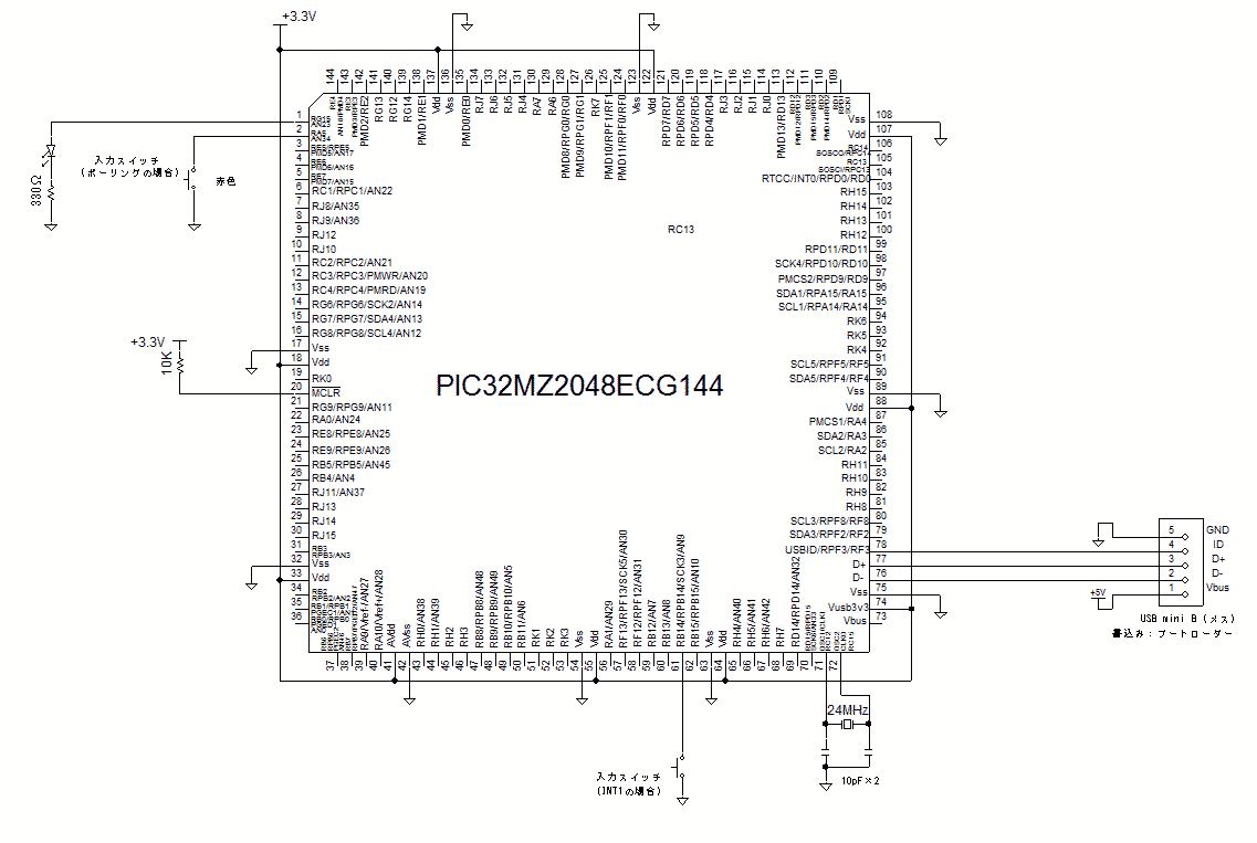
< PIC32MZ + Harmony 編 >
(タイマを使ったポーリング方式)
PIC32MZ2048ECH144 XC32コンパイラの場合の例を紹介します。
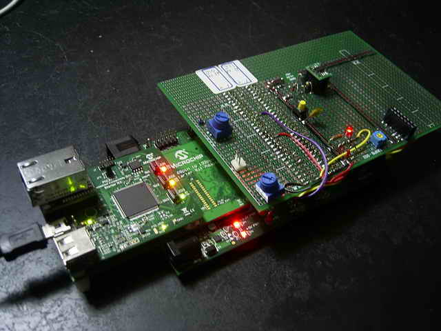
<試作品の仕様>
1. ハード
・ PIC: PIC32MZ2048ECH144 rev.3( at Microchip PIC32MZ Embedded
Connectivity (EC) Starter Kit)、
Microchip 168pin to 132pin Adaptor board、 I/O Expansion board 及び ユニバーサルキバンのキバン構成とする。
2. 開発環境
Harmony Ver.1.00、 XC32
Ver.1.33 、 MPLABX Ver.2.15、USBブートローダ書込み
3. ソフトの仕様
 ・押しボタンスイッチ操作による LEDの点灯と消灯の繰り返し
<試作品回路図>(→回路図のPDFファイル)
<試作品の外観> 下記の写真には上記回路図にはない、また本テーマと関係のない部品が多々写っています
   <プログラム例>
//以下、main.c
//---------------------------------------------------------------------------------------------
/*******************************************************************************
  MPLAB Harmony Project Main Source File

  Company:
    Microchip Technology Inc.

  File Name:
    main.c

  Summary:
    This file contains the "main" function for an MPLAB Harmony project.

  Description:
    This file contains the "main" function for an MPLAB Harmony project.  The
    "main" function calls the "SYS_Initialize" function to initialize the state
    machines of all MPLAB Harmony modules in the system and it calls the
    "SYS_Tasks" function from within a system-wide "super" loop to maintain
    their correct operation. These two functions are implemented in
    configuration-specific files (usually "system_init.c" and "system_tasks.c")
    in a configuration-specific folder under the "src/system_config" folder
    within this project's top-level folder.  An MPLAB Harmony project may have
    more than one configuration, each contained within it's own folder under
    the "system_config" folder.
 *******************************************************************************/

// DOM-IGNORE-BEGIN
/*******************************************************************************
Copyright (c) 2013-2014 released Microchip Technology Inc.  All rights reserved.

//Microchip licenses to you the right to use, modify, copy and distribute
Software only when embedded on a Microchip microcontroller or digital signal
controller that is integrated into your product or third party product
(pursuant to the sublicense terms in the accompanying license agreement).

You should refer to the license agreement accompanying this Software for
additional information regarding your rights and obligations.

SOFTWARE AND DOCUMENTATION ARE PROVIDED "AS IS" WITHOUT WARRANTY OF ANY KIND,
EITHER EXPRESS OR IMPLIED, INCLUDING WITHOUT LIMITATION, ANY WARRANTY OF
MERCHANTABILITY, TITLE, NON-INFRINGEMENT AND FITNESS FOR A PARTICULAR PURPOSE.
IN NO EVENT SHALL MICROCHIP OR ITS LICENSORS BE LIABLE OR OBLIGATED UNDER
CONTRACT, NEGLIGENCE, STRICT LIABILITY, CONTRIBUTION, BREACH OF WARRANTY, OR
OTHER LEGAL EQUITABLE THEORY ANY DIRECT OR INDIRECT DAMAGES OR EXPENSES
INCLUDING BUT NOT LIMITED TO ANY INCIDENTAL, SPECIAL, INDIRECT, PUNITIVE OR
CONSEQUENTIAL DAMAGES, LOST PROFITS OR LOST DATA, COST OF PROCUREMENT OF
SUBSTITUTE GOODS, TECHNOLOGY, SERVICES, OR ANY CLAIMS BY THIRD PARTIES
(INCLUDING BUT NOT LIMITED TO ANY DEFENSE THEREOF), OR OTHER SIMILAR COSTS.
 *******************************************************************************/
// DOM-IGNORE-END


// *****************************************************************************
// *****************************************************************************
// Section: Included Files
// *****************************************************************************
// *****************************************************************************

#include <stddef.h>                     // Defines NULL
#include <stdbool.h>                    // Defines true
#include <stdlib.h>                     // Defines EXIT_FAILURE
#include "system/common/sys_module.h"   // SYS function prototypes


// *****************************************************************************
// *****************************************************************************
// Section: Main Entry Point
// *****************************************************************************
// *****************************************************************************

int main ( void )
{
    /* Initialize all MPLAB Harmony modules, including application(s). */
    SYS_Initialize ( NULL );

    while ( true )
    {
        /* Maintain state machines of all polled MPLAB Harmony modules. */
        SYS_Tasks ( );

    }

    /* Execution should not come here during normal operation */

    return ( EXIT_FAILURE );
}


/*******************************************************************************
 End of File
*/


//以下、app.c
//------------------------------------------------------------------------------------------------
/*******************************************************************************
  MPLAB Harmony Application Source File

  Company:
    Microchip Technology Inc.

  File Name:
    app.c

  Summary:
    This file contains the source code for the MPLAB Harmony application.

  Description:
    This file contains the source code for the MPLAB Harmony application.  It
    implements the logic of the application's state machine and it may call
    API routines of other MPLAB Harmony modules in the system, such as drivers,
    system services, and middleware.  However, it does not call any of the
    system interfaces (such as the "Initialize" and "Tasks" functions) of any of
    the modules in the system or make any assumptions about when those functions
    are called.  That is the responsibility of the configuration-specific system
    files.
 *******************************************************************************/

// DOM-IGNORE-BEGIN
/*******************************************************************************
Copyright (c) 2013-2014 released Microchip Technology Inc.  All rights reserved.

Microchip licenses to you the right to use, modify, copy and distribute
Software only when embedded on a Microchip microcontroller or digital signal
controller that is integrated into your product or third party product
(pursuant to the sublicense terms in the accompanying license agreement).

You should refer to the license agreement accompanying this Software for
additional information regarding your rights and obligations.

SOFTWARE AND DOCUMENTATION ARE PROVIDED "AS IS" WITHOUT WARRANTY OF ANY KIND,
EITHER EXPRESS OR IMPLIED, INCLUDING WITHOUT LIMITATION, ANY WARRANTY OF
MERCHANTABILITY, TITLE, NON-INFRINGEMENT AND FITNESS FOR A PARTICULAR PURPOSE.
IN NO EVENT SHALL MICROCHIP OR ITS LICENSORS BE LIABLE OR OBLIGATED UNDER
CONTRACT, NEGLIGENCE, STRICT LIABILITY, CONTRIBUTION, BREACH OF WARRANTY, OR
OTHER LEGAL EQUITABLE THEORY ANY DIRECT OR INDIRECT DAMAGES OR EXPENSES
INCLUDING BUT NOT LIMITED TO ANY INCIDENTAL, SPECIAL, INDIRECT, PUNITIVE OR
CONSEQUENTIAL DAMAGES, LOST PROFITS OR LOST DATA, COST OF PROCUREMENT OF
SUBSTITUTE GOODS, TECHNOLOGY, SERVICES, OR ANY CLAIMS BY THIRD PARTIES
(INCLUDING BUT NOT LIMITED TO ANY DEFENSE THEREOF), OR OTHER SIMILAR COSTS.
 *******************************************************************************/
// DOM-IGNORE-END


// *****************************************************************************
// *****************************************************************************
// Section: Included Files
// *****************************************************************************
// *****************************************************************************

#include "app.h"

# ifndef _MY_INCLUDE_PERIPHERAL
#define   _MY_INCLUDE_PERIPHERAL
#include <peripheral/peripheral.h>
#include <peripheral/ports/plib_ports.h>
#endif


// *****************************************************************************
// *****************************************************************************
// Section: Global Data Definitions
// *****************************************************************************
// *****************************************************************************

// *****************************************************************************
/* Application Data

  Summary:
    Holds application data

  Description:
    This structure holds the application's data.

  Remarks:
    This structure should be initialized by the APP_Initialize function.

    Application strings and buffers are be defined outside this structure.
*/

APP_DATA appData;


// *****************************************************************************
// *****************************************************************************
// Section: Application Callback Functions
// *****************************************************************************
// *****************************************************************************

/* TODO:  Add any necessary callback funtions.
*/


// *****************************************************************************
// *****************************************************************************
// Section: Application Local Functions
// *****************************************************************************
// *****************************************************************************

/* TODO:  Add any necessary local functions.
*/


// *****************************************************************************
// *****************************************************************************
// Section: Application Initialization and State Machine Functions
// *****************************************************************************
// *****************************************************************************

/*******************************************************************************
  Function:
    void APP_Initialize ( void )

  Remarks:
    See prototype in app.h.
 */

void APP_Initialize ( void )
{
    /* Place the App state machine in its initial state. */
    appData.state = APP_STATE_INIT;

    /* TODO: Initialize your application's state machine and other
     * parameters.
     */


    //SWポート設定

    PLIB_PORTS_PinDirectionInputSet( PORTS_ID_0, PORT_CHANNEL_A, 5 );  //SWポート:RB14  入力モード
    //TRISAbits.TRISA5 = 1;  //SWポート:RA5  入力モード

    PLIB_PORTS_PinModeSelect(PORTS_ID_0, PORTS_ANALOG_PIN_34, PORTS_PIN_MODE_DIGITAL);   //RA5/AN34ポートをデジタルモードに設定
    //ANSELAbits.ANSA5 = 0;  //SWポート:RA5 デジタルモード

    PLIB_PORTS_ChangeNoticePullUpPerPortEnable(PORTS_ID_0, PORT_CHANNEL_A, PORTS_BIT_POS_5); //SWポート:RA5 プルアップ抵抗設定
    //CNPUAbits.CNPUA5 = 1;  //SWポート:RA5 プルアップ抵抗設定


    //LEDポート設定
    PLIB_PORTS_PinDirectionOutputSet( PORTS_ID_0, PORT_CHANNEL_G, 15 );    //LEDポート:RG15: 出力モード
    //TRISGbits.TRISG15 = 0;  //LEDポート: 出力モード

    //初期設定
    PLIB_PORTS_PinClear( PORTS_ID_0, PORT_CHANNEL_G, 15 ); //LEDポート:  RG15: 消灯
    //LATGbits.LATG15 = 0;    //LEDポート:  RG15: 消灯
}


/******************************************************************************
  Function:
    void APP_Tasks ( void )

  Remarks:
    See prototype in app.h.
 */

void APP_Tasks ( void )
{
    /* Check the application's current state. */
    switch ( appData.state )
    {
        /* Application's initial state. */
        case APP_STATE_INIT:
        {
            break;
        }

        /* TODO: implement your application state machine.*/

        /* The default state should never be executed. */
        default:
        {
            /* TODO: Handle error in application's state machine. */
            break;
        }
    }
}


/*******************************************************************************
 End of File
 */


//以下、system_init.c
//-------------------------------------------------------------------------------------------
/*******************************************************************************
  System Initialization File

  File Name:
    system_init.c

  Summary:
    This file contains source code necessary to initialize the system.

  Description:
    This file contains source code necessary to initialize the system.  It
    implements the "SYS_Initialize" function, configuration bits, and allocates
    any necessary global system resources, such as the systemObjects structure
    that contains the object handles to all the MPLAB Harmony module objects in
    the system.
 *******************************************************************************/

// DOM-IGNORE-BEGIN
/*******************************************************************************
Copyright (c) 2013-2014 released Microchip Technology Inc.  All rights reserved.

Microchip licenses to you the right to use, modify, copy and distribute
Software only when embedded on a Microchip microcontroller or digital signal
controller that is integrated into your product or third party product
(pursuant to the sublicense terms in the accompanying license agreement).

You should refer to the license agreement accompanying this Software for
additional information regarding your rights and obligations.

SOFTWARE AND DOCUMENTATION ARE PROVIDED AS IS WITHOUT WARRANTY OF ANY KIND,
EITHER EXPRESS OR IMPLIED, INCLUDING WITHOUT LIMITATION, ANY WARRANTY OF
MERCHANTABILITY, TITLE, NON-INFRINGEMENT AND FITNESS FOR A PARTICULAR PURPOSE.
IN NO EVENT SHALL MICROCHIP OR ITS LICENSORS BE LIABLE OR OBLIGATED UNDER
CONTRACT, NEGLIGENCE, STRICT LIABILITY, CONTRIBUTION, BREACH OF WARRANTY, OR
OTHER LEGAL EQUITABLE THEORY ANY DIRECT OR INDIRECT DAMAGES OR EXPENSES
INCLUDING BUT NOT LIMITED TO ANY INCIDENTAL, SPECIAL, INDIRECT, PUNITIVE OR
CONSEQUENTIAL DAMAGES, LOST PROFITS OR LOST DATA, COST OF PROCUREMENT OF
SUBSTITUTE GOODS, TECHNOLOGY, SERVICES, OR ANY CLAIMS BY THIRD PARTIES
(INCLUDING BUT NOT LIMITED TO ANY DEFENSE THEREOF), OR OTHER SIMILAR COSTS.
 *******************************************************************************/
// DOM-IGNORE-END


// *****************************************************************************
// *****************************************************************************
// Section: Included Files
// *****************************************************************************
// *****************************************************************************

#include "system_config.h"
#include "app.h"
#include "system_definitions.h"


// ****************************************************************************
// ****************************************************************************
// Section: Configuration Bits
// ****************************************************************************
// ****************************************************************************

//コンフィグ設定
// DEVCFG0
#pragma config EJTAGBEN = NORMAL
#pragma config DBGPER = ALLOW_PG2
#pragma config FSLEEP = OFF
#pragma config FECCCON = OFF_UNLOCKED
#pragma config BOOTISA = MIPS32
#pragma config TRCEN = OFF
#pragma config ICESEL = ICS_PGx2
#pragma config JTAGEN = OFF //JTAG ポート Disable
#pragma config DEBUG = ON


// DEVCFG1
#pragma config FNOSC = SPLL //発振器選択:システム発振回路 //内蔵FRC(8MHz)の場合:FNOSC = FRCDIV   //Oscillator Selection Bits (Fast RC Osc w/Div-by-N (FRCDIV))
#pragma config DMTINTV = WIN_127_128 // DMT Count Window Interval (Window/Interval value is 127/128 counter value)
#pragma config FSOSCEN = OFF // Secondary Oscillator Enable (Disable SOSC)
#pragma config IESO = OFF // Internal/External Switch Over (Disabled)
#pragma config POSCMOD = EC // Primary Oscillator Configuration (Primary osc disabled)
#pragma config OSCIOFNC = ON // CLKO Output Signal Active on the OSCO Pin (Enabled)
#pragma config FCKSM = CSDCMD // Clock Switching and Monitor Selection (Clock Switch Disabled, FSCM Disabled)
#pragma config WDTPS = PS1048576 // Watchdog Timer Postscaler (1:1048576)
#pragma config WDTSPGM = STOP // Watchdog Timer Stop During Flash Programming (WDT stops during Flash programming)
#pragma config WINDIS = NORMAL // Watchdog Timer Window Mode (Watchdog Timer is in non-Window mode)
#pragma config FWDTEN = OFF // Watchdog Timer Disable
#pragma config FWDTWINSZ = WINSZ_25 // Watchdog Timer Window Size (Window size is 25%)
// DMTCNT = No Setting
#pragma config FDMTEN = OFF // Deadman Timer Enable (Deadman Timer is disabled)


//システムクロック:200MHz
//ペリフェラル周波数:100MHz    // default: システムクロックの1/2
//PBxDIV: PERIPHERAL BUS CLOCK DIVISOR CONTROL レジスタのPBDIV<6:0>: Peripheral Bus Clock Divisor Control ビットで設定    //1/1 ? 1/128
//DEVCFG2
#pragma config FPLLIDIV = DIV_3 // 1/3  // PLL Input周波数 = 24MHz ÷ 3 = 8MHz     // System PLL Input Divider (1x Divider)
#pragma config FPLLRNG = RANGE_5_10_MHZ //PLL周波数入力範囲設定// System PLL Input Range (5-10 MHz Input)  //8MHz故
#pragma config FPLLICLK = PLL_POSC //主発振回路選択 //内蔵FRC(8MHz)の場合はFPLLICLK = PLL_FRC//  System PLL Input Clock Selection (POSC is input to the System PLL)
#pragma config FPLLMULT = MUL_50 //PLL倍率:50倍 //8MHz x 50 = 400MHz  //System PLL Multiplier (PLL Multiply by 50)
#pragma config FPLLODIV = DIV_2 // 1/2  //システムクロック = 400MHz ÷ 2 = 200MHz
#pragma config UPLLFSEL = FREQ_24MHZ //USBのPLL入力を 24MHz→12MHzに変換 // USB PLL Input Frequency Selection (USB PLL input is 12 MHz)
#pragma config UPLLEN = ON //USBのPLL変換:イネーブル // USB PLL Enable (USB PLL is enabled)


// DEVCFG3
//イーサネット  // USERID = No Setting
#pragma config FMIIEN = ON // Ethernet RMII/MII Enable (MII Enabled)
#pragma config FETHIO = ON // Ethernet I/O Pin Select (Default Ethernet I/O)
#pragma config PGL1WAY = ON // Permission Group Lock One Way Configuration (Allow only one reconfiguration)
#pragma config PMDL1WAY = ON // Peripheral Module Disable Configuration (Allow only one reconfiguration)
#pragma config IOL1WAY = ON // Peripheral Pin Select Configuration (Allow only one reconfiguration)
#pragma config FUSBIDIO = OFF // USB USBID Selection (Controlled by Port Function)

/*** BF1SEQ0 ***/

#pragma config TSEQ =       0xffff
#pragma config CSEQ =       0xffff


// *****************************************************************************
// *****************************************************************************
// Section: Library/Stack Initialization Data
// *****************************************************************************
// *****************************************************************************/


// *****************************************************************************
// *****************************************************************************
// Section: Driver Initialization Data
// *****************************************************************************
// *****************************************************************************


// *****************************************************************************
// *****************************************************************************
// Section: System Data
// *****************************************************************************
// *****************************************************************************

/* Structure to hold the object handles for the modules in the system. */
SYSTEM_OBJECTS sysObj;

// *****************************************************************************
// *****************************************************************************
// Section: Module Initialization Data
// *****************************************************************************
// *****************************************************************************

// *****************************************************************************
/* System Clock Initialization Data
*/

const SYS_CLK_INIT sysClkInit =
{
    .moduleInit = {0},
    .systemClockSource = SYS_CLK_SOURCE,
    .systemClockFrequencyHz = SYS_CLK_FREQ,
    .waitTillComplete = true,
    .secondaryOscKeepEnabled = true,
    .onWaitInstruction = SYS_CLK_ON_WAIT,
};


/*** System Device Control Initialization Data ***/

const SYS_DEVCON_INIT sysDevconInit =
{
    .moduleInit = {0},
};


// *****************************************************************************
// *****************************************************************************
// Section: Static Initialization Functions
// *****************************************************************************
// *****************************************************************************

/*******************************************************************************
  Function:
    void DRV_TMR0_Initialize(void)

  Summary:
    Initializes Timer Driver Instance 0

  Remarks:
 */
void DRV_TMR0_Initialize(void)
{
    /* Setup TMR0 Instance */
    PLIB_TMR_Stop(TMR_ID_2); /* Disable Timer */
    PLIB_TMR_ClockSourceSelect(TMR_ID_2, TMR_CLOCK_SOURCE_PERIPHERAL_CLOCK); /* Select clock source */
    PLIB_TMR_PrescaleSelect(TMR_ID_2, TMR_PRESCALE_VALUE_64); /* Select prescalar value */
    PLIB_TMR_Mode16BitEnable(TMR_ID_2); /* Enable 16 bit mode */
    PLIB_TMR_Counter16BitClear(TMR_ID_2); /* Clear counter */
    PLIB_TMR_Period16BitSet(TMR_ID_2, 0); /*Set period */

    /* Setup Interrupt */
    PLIB_INT_SourceEnable(INT_ID_0, INT_SOURCE_TIMER_2);
    PLIB_INT_VectorPrioritySet(INT_ID_0, INT_VECTOR_T2, INT_PRIORITY_LEVEL2);
    PLIB_INT_VectorSubPrioritySet(INT_ID_0, INT_VECTOR_T2, INT_SUBPRIORITY_LEVEL0);

    PLIB_TMR_Period16BitSet(TMR_ID_2,15625);    //5 nsec x2  x 15625 x 64 = 10000000μsec = 10msec
    PLIB_TMR_Start(TMR_ID_2);    //タイマ2 スタート
}

// *****************************************************************************
// *****************************************************************************
// Section: System Initialization
// *****************************************************************************
// *****************************************************************************

/*******************************************************************************
  Function:
    void SYS_Initialize ( SYS_INIT_DATA *data )

  Summary:
    Initializes the board, services, drivers, application and other modules.

  Remarks:
    See prototype in system/common/sys_module.h.
 */

void SYS_Initialize ( void* data )
{
    /* Core Processor Initialization */
    SYS_CLK_Initialize(&sysClkInit);
    sysObj.sysDevcon = SYS_DEVCON_Initialize(SYS_DEVCON_INDEX_0, (SYS_MODULE_INIT*)&sysDevconInit);
    SYS_DEVCON_PerformanceConfig(SYS_DEVCON_SYSTEM_CLOCK);

    /* System Services Initialization */
    SYS_INT_Initialize();

    /* Initialize Drivers */
    /* Timer Instanace 0 Call */
    DRV_TMR0_Initialize();


    /* Initialize System Services */

    /* Initialize Middleware */

    /* Enable Global Interrupts */
    SYS_INT_Enable();

    /* Initialize the Application */
    APP_Initialize();
}

/*******************************************************************************
 End of File
*/


//以下、system_interrupt.c
//-------------------------------------------------------------------------------------------
/*******************************************************************************
 System Interrupts File

  File Name:
    system_int.c

  Summary:
    Raw ISR definitions.

  Description:
    This file contains a definitions of the raw ISRs required to support the
    interrupt sub-system.

  Summary:
    This file contains source code for the interrupt vector functions in the
    system.

  Description:
    This file contains source code for the interrupt vector functions in the
    system.  It implements the system and part specific vector "stub" functions
    from which the individual "Tasks" functions are called for any modules
    executing interrupt-driven in the MPLAB Harmony system.

  Remarks:
    This file requires access to the systemObjects global data structure that
    contains the object handles to all MPLAB Harmony module objects executing
    interrupt-driven in the system.  These handles are passed into the individual
    module "Tasks" functions to identify the instance of the module to maintain.
 *******************************************************************************/

// DOM-IGNORE-BEGIN
/*******************************************************************************
Copyright (c) 2011-2014 released Microchip Technology Inc.  All rights reserved.

Microchip licenses to you the right to use, modify, copy and distribute
Software only when embedded on a Microchip microcontroller or digital signal
controller that is integrated into your product or third party product
(pursuant to the sublicense terms in the accompanying license agreement).

You should refer to the license agreement accompanying this Software for
additional information regarding your rights and obligations.

SOFTWARE AND DOCUMENTATION ARE PROVIDED "AS IS" WITHOUT WARRANTY OF ANY KIND,
EITHER EXPRESS OR IMPLIED, INCLUDING WITHOUT LIMITATION, ANY WARRANTY OF
MERCHANTABILITY, TITLE, NON-INFRINGEMENT AND FITNESS FOR A PARTICULAR PURPOSE.
IN NO EVENT SHALL MICROCHIP OR ITS LICENSORS BE LIABLE OR OBLIGATED UNDER
CONTRACT, NEGLIGENCE, STRICT LIABILITY, CONTRIBUTION, BREACH OF WARRANTY, OR
OTHER LEGAL EQUITABLE THEORY ANY DIRECT OR INDIRECT DAMAGES OR EXPENSES
INCLUDING BUT NOT LIMITED TO ANY INCIDENTAL, SPECIAL, INDIRECT, PUNITIVE OR
CONSEQUENTIAL DAMAGES, LOST PROFITS OR LOST DATA, COST OF PROCUREMENT OF
SUBSTITUTE GOODS, TECHNOLOGY, SERVICES, OR ANY CLAIMS BY THIRD PARTIES
(INCLUDING BUT NOT LIMITED TO ANY DEFENSE THEREOF), OR OTHER SIMILAR COSTS.
 *******************************************************************************/
// DOM-IGNORE-END


// *****************************************************************************
// *****************************************************************************
// Section: Included Files
// *****************************************************************************
// *****************************************************************************

#include <xc.h>
#include <sys/attribs.h>
#include "app.h"
#include "system_definitions.h"

# ifndef _MY_INCLUDE_PERIPHERAL
#define   _MY_INCLUDE_PERIPHERAL
#include <peripheral/peripheral.h>
#include <peripheral/ports/plib_ports.h>
#endif

int Count_Sw = 0;
int Count_SwDetect = 10;    //スイッチ押し検出判定回数  //チャタリング防止


// *****************************************************************************
// *****************************************************************************
// Section: System Interrupt Vector Functions
// *****************************************************************************
// *****************************************************************************
void __ISR(_TIMER_2_VECTOR, ipl2) _IntHandlerDrvTmrInstance0(void)
{
    PLIB_INT_SourceFlagClear(INT_ID_0,INT_SOURCE_TIMER_2);
    //IFS0bits.T2IF = 0;  // タイマ2割り込みフラグクリア
    PLIB_TMR_Period16BitSet(TMR_ID_2,15625);    //5 nsec x2  x 15625 x 64 = 10000000μsec = 10msec


    if(PLIB_PORTS_PinGet(PORTS_ID_0, PORT_CHANNEL_A, PORTS_BIT_POS_5) == 0)Count_Sw++;  //RA5読込・判定
    //    if(PORTAbits.RA5 == 0)Count_Sw++;

    else Count_Sw = 0;
    if(Count_Sw == Count_SwDetect)  //チャタリング防止
    {
        PLIB_PORTS_Toggle(PORTS_ID_0, PORT_CHANNEL_G, 0x8000);  //ポート反転
        //LATG ^= 0x8000;     //RG15 反転     //0b1000000000000000
    }
    if(Count_Sw >= (Count_SwDetect +1))Count_SwDetect +1;   //長くスイッチが押された場合のオーバーフロー防止
}


/*******************************************************************************
 End of File
*/
(3) 外部割込みを使ってスイッチ信号を検出する方法
<CCS編> ************************************************************************************
モメンタリスイッチによるLEDのON/OFF *************************************************************
RB0ポートからのINT割込みを紹介します。
<試作品回路図> (→回路図のPDFファイル)

 <プログラム例><CCS編> 外部割込みによる方法 PICは16F84です

#include <16F84a.h>
#use delay(clock=10000000)
#FUSES  HS,NOWDT,NOPROTECT,PUT
short int Led= 0;                           //LEDモード : LEDが点灯の場合”1”、消灯の場合”0”


#int_ext
void ioRead()
{
        disable_interrupts(INT_EXT);          //チャタリングしている間割込みを禁止する
        disable_interrupts(GLOBAL);
        delay_ms(50);                          //50msecの間待つ
        if(input(PIN_B0) == 0)                 //RB0ポートをチェックして ”0”なら
        {
                if(Led == 1)                   //LEDが点灯していたのなら
                {
                        Led = 0;                                //LEDのモードを消灯モードにセットして
                        output_high(PIN_A2);   //RA2ポートをHigh(5v)にしてLEDを消灯する
                }
                else                            // またLEDが消灯していたなら
                {
                        Led = 1;                // LEDのモードを点灯モードにセットして
                        output_low(PIN_A2);     // RA2ポートをLow(0v)にしてLEDを点灯する
                }
        }
        enable_interrupts(INT_EXT);              //R0からの外部割込みを許可
        enable_interrupts(GLOBAL);               // すべての割り込みを許可

}


main()
{
        ext_int_edge(H_TO_L);                   // RB0ポートが highからlowに変化した時割込みがかかるように設定
        enable_interrupts(INT_EXT);             //RB0からの外部割込みを許可
        enable_interrupts(GLOBAL);              // すべての割り込みを許可

        Led = 0;
        output_high(PIN_A2);                    // 電源投入でLED消灯

        while(1)                                //割込みが発生する以外は何もしないで待つ
        {
        }

        return 0;
}
<HI−TECH 編> 外部割り込みによるモメンタリスイッチによるLED ON/OFF
① PIC16F877のRB0ポートからのINT割込み例を紹介します。
<試作品回路図> (→回路図のPDFファイル)
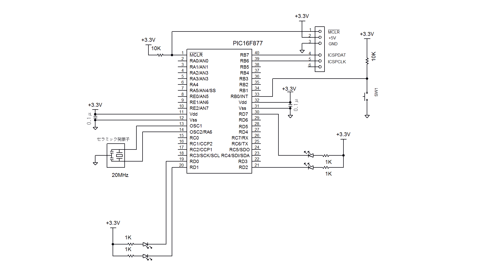
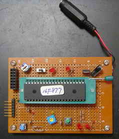
<試作品外観>下記の写真には上記回路図にはない、また本テーマと関係のない部品が多々写っています
   <プログラム例>

//HI-TECH
// PIC16F877  LED Momentary SW ON_OFF

#include  <htc.h>

#define _XTAL_FREQ 20000000             //Ceramic :20MHz

__CONFIG(
        PWRTEN          //  enable power up timer
        & BORDIS        // enable brown out reset
        & UNPROTECT     //use UNPROTECT
        & WDTDIS        // No Watchdog Timer
        & LVPDIS        // low voltage programming disabled
        & HS            // EXTRC Oscillator, RC on RA7/OSC1/CLKIN
        );


short int Led = 0;       //LED Mode : LED On_Mode = 1, LED Off_Mode = 0


void delay_ms(unsigned long int msec)        //1msec delay function
{
        while(msec)
        {
                msec--;
                __delay_ms(1);  //1msec delay
         }
}


void interrupt ISR(void)
{
                INTE = 0; // ext INT Disable
        PEIE = 0;       //Peripheral INT  Disable
        GIE = 0;   // Gloval INT Disable

        delay_ms(50);

        if(RB0 == 0)
        {
                if(Led == 0)         //if LED Not Lighed
                {

                        Led = 1;          //LED Mode : LED ON Mode
                        RD0 = 0;        // LED Turn ON


                }
                else             //if LED Lighted
                {
                        Led = 0;     //LED Mode : LED OFF Mode
                        RD0 = 1;      //RD0 port LED Turn off

                }

        }
        INTF = 0;       // LED Flag Clear
        INTE = 1;       // ext INT Enable
    PEIE = 0;  // Peripheral INT Disable
    GIE = 1;   //Gloval INT Enable

}


int main()
{
        TRISB = 0x01;
        TRISD = 0;      //D port: outport
        TRISC = 0xFF;           // C port inport

        INTEDG = 0;     // Down Edge Trigger

        Led = 0;    //LED Mode : OFF Mode
        RD0 = 1;    //RD0 port LED Turn off


        INTF = 0; //INT Flag Clear
        INTE = 1;       //ext-INT Enable
        PEIE = 0;  // Peripheral INT Disable
        GIE = 1; // Gloval INT Enable

        while(1)
        {
        }

        return 0;

}
② PIC16F1937のRB0ポートからのINT割込み例を紹介します。
<試作品回路図> (→回路図のPDFファイル)
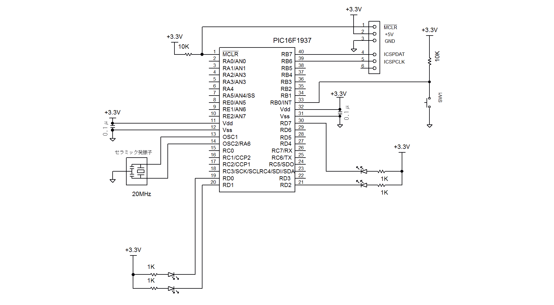
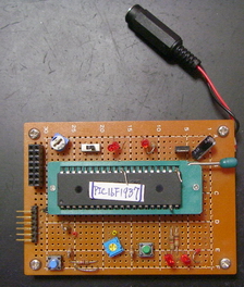
<試作品外観>下記の写真には上記回路図にはない、また本テーマと関係のない部品が多々写っています
   <プログラム例>

//HI-TEC LED  Momentary SW ON_OFF
//  External int                          PIC16F1937

#include  <htc.h>

#define _XTAL_FREQ 20000000             //Ceramic :20MHz

//Configuration
__CONFIG(
                FOSC_HS &                       // EXTRC Oscillator, RC on RA7/OSC1/CLKIN
                WDTE_OFF &              // Power-up Timer Enable bit// PWRT disabled
                PWRTE_ON &              // MCLR Pin Function Select// RE3/MCLR/VPP pin function is MCLR
                MCLRE_ON &              // RE3/MCLR/VPP pin function is digital input
                CP_OFF  &               // Program memory code protection is enabled
                CPD_OFF &               // Data memory code protection is enabled
                BOREN_OFF &             // Clock Out Enable bit// CLKOUT function is disabled. I/O or oscillator function on RA6/CLKOUT
                CLKOUTEN_OFF &  // CLKOUT function is enabled on RA6/CLKOUT pin
                IESO_OFF &              // Fail Clock Monitor Enable// Fail-Safe Clock Monitor is enabled
                FCMEN_ON                // Fail-Safe Clock Monitor is disabled
                );


__CONFIG(
                WRT_OFF &       // 000h to 1FFh write protected, 200h to 1FFFh may be modified by EECON control
                PLLEN_OFF &     // 4x PLL disabled
                STVREN_OFF &// Brown-out Reset Voltage selection// Brown-out Reset Voltage (VBOR) set to 1.9 V
                BORV_19 &       // Brown-out Reset Voltage (VBOR) set to 2.7 V
//              DEBUG_OFF &     // Background debugger is enabled
                LVP_OFF         // HV on MCLR/VPP must not be used for programming
                );


short int Led = 0;       //LED mode : LED On:1 LED OFF:0

void delay_ms(unsigned long int msec)        //1msec delay function
{
        while(msec)
        {
                msec--;
                __delay_ms(1);  //1msec delay

        }
}


void interrupt ISR(void)
{


                INTE = 0;       //ext INT Disable
        PEIE = 0;       //Peripheral INT Disable
        GIE = 0;        //Gloval INT Disable

        delay_ms(50);

        if(PORTBbits.RB0 == 0)
        {
                if(Led == 0)    //if LED Not Lighted
                {

                        Led = 1;
                        LATD0 = 0;      //   LED: Turn on


                }
                else  //if LED Lighted
                {
                        Led = 0;
                        LATD0 = 1;   //LED : Turn off

                }

        }
        INTF = 0;       //INT Flag clear
        INTE = 1;       //INT Enable
    PEIE = 0;   // Peripheral INT Disable
    GIE = 1;    //Gloval INT Enable


/*
        INTE = 0;       //ext INT Disable
        PEIE = 0;       //Peripheral INT Disable
        GIE = 0;        //Gloval INT Disable


  if (INTF) {
    INTF = 0;  //reset intf


   RD0 = RD0 ^ 1;  //flip rd0
        //LATD0 = LATD0 ^ 1;


  }


        INTF = 0;       //INT Flag clear
        INTE = 1;       //INT Enable
    PEIE = 0;   // Peripheral INT Disable
    GIE = 1;    //Gloval INT Enable

*/


}


int main()
{
        TRISB = 0x01;   //RB0: in port
        TRISD = 0;      //D port: outport

        ANSELB = 0;     //PIC16F1937 のBポートははデフォルトではアナログモードなのでデジタルモードに変換
        ANSELD = 0;     //PIC16F1937 のDポートははデフォルトではアナログモードなのでデジタルモードに変換

        INTEDG = 0;     //down edge

        Led = 0;           //LED Mode: OFF Mode
        LATD0 = 1;        //RD0 port LED off

        INTF = 0;       //INT Flag clear
        INTE = 1;       //ext INT Enable
        PEIE = 0;   // Peripheral INT Disable
        GIE = 1;    // Gloval INT Enable

        while(1)
        {
        }
        return 0;
}
<C18編> ***************************************************************************************:
モメンタリスイッチによるLEDのON/OFF *************************************************************
RB2からのINT2割込みを紹介します。
<試作品回路図>(→回路図のPDFファイル)
PIC18F4550を使用した例を以下に示します
  <プログラム例><C18編> 外部割込みによる方法
/*
オルタネートスイッチ
      外部割込みINT2による
                        LED ON/OFF
*/

#include <p18f4550.h>
#include <portb.h>
#include <delays.h>


#pragma config PLLDIV = 5            //96MHz PLL Prescalar(1、2、3、4、5、6、10、12のみ) : 外部周波数÷4MHz
                                     //20MHz ÷ 5 = 4MHz → 96MHz(=4MHz×24 :固定)
#pragma config USBDIV = 2            // Full Speed USB Clock Source Selection : 2(constant)
#pragma config CPUDIV = OSC1_PLL2    //CPU System Clock Postscaler
                                     // PICのUSB制御用クロック周波数:48MHz(=96MHz ÷2)
#pragma config FOSC = HS             // システムクロック=20MHz
//#pragma config FOSC = HSPLL_HS     // システムクロック=48MHz

#pragma config WDT = OFF             //ウォッチドックタイマOFF
#pragma config LVP = OFF             //低電圧書き込みOFF
#pragma config PWRT = ON             //パワーアップタイマON
#pragma config BOR = ON              //ブラウンアウトリセットON(ハードウェアのみ)
#pragma config BORV = 1              //Brown out Voltage = 4.33v
                                     // ref: BORV=0 → 4.59v    BORV=2 → 2.79v  BORV=4 → 2.05v
#pragma config PBADEN = OFF          //リセットでポートBの全アナログポートをデジタルI/Oにリセット
                                     // PORTB A/D Enable bit = 0 (CONFIG3H)


int Led= 0;                           //LEDモード : LEDが点灯の場合”1”、消灯の場合”0”

void delay_ms(long int);
void int_portRB2();


void delay_ms (long int cycle)                        // CCSコンパイラと同じ delay_ms(long int) 関数を設計
{
        long int i = 0;
        for (i = 0; i < cycle; i++)Delay1KTCYx(5);    // 0.05μsec × 4 × 5000 = 1msec システムクロック=20Mhz
}

#pragma code low_vector=0x8                           //高位レベル割込み
void low_interrupt (void)
{
        _asm GOTO int_portRB2 _endasm
}
#pragma code
#pragma interruptlow int_portRB2


void int_portRB2()                // 外部割込み関数
{

                                  //チャタリングしている間割込みを禁止する
        INTCON3bits.INT2IE = 0;   //外部割込みINT2の禁止
//      INTCONbits.PEIE = 0;      //低位割込み禁止
        INTCONbits.GIE = 0;       //全割込み禁止

        INTCON3bits.INT2IF = 0;   // INT2の割込みフラグをリセット

        delay_ms(50);             //50msecの間待つ

        if(PORTBbits.RB2 == 0)    //RB2ポートをチェックして ”0”なら
        {
                if(Led == 1)                   //LEDが点灯していたのなら
                {
                        Led = 0;               //LEDのモードを消灯モードにセットして
                        LATBbits.LATB4 =1;     //RB4ポートをHigh(5v)にしてLEDを消灯する
                }
                else                            // またLEDが消灯していたなら
                {
                        Led = 1;                // LEDのモードを点灯モードにセットして
                        LATBbits.LATB4 = 0;     // RB4ポートをLow(0v)にしてLEDを点灯する
                }
        }

        INTCON3bits.INT2IE = 1;   //外部割込みINT2の許可
//      INTCONbits.PEIE = 1;      //低位割込み許可
        INTCONbits.GIE = 1;       //全割込み許可
}


void main(void)
{
        TRISB = 0b00000100;                                     // B portのRB2を入力モードに その他を出力モードに設定

        OpenRB2INT(PORTB_CHANGE_INT_ON &                        //ポートRB2の外部割込みON
                                FALLING_EDGE_INT &              //立下りエッジでON
                                PORTB_PULLUPS_OFF               //Bポートの抵抗プルアップOFF
                                );
        RCONbits.IPEN = 1;      //割込み優先順位制御ON  (0:優先順位制御OFF)
        INTCON3bits.INT2IP = 1; //INT2の割り込みを高位割込みにセット(0:低位割込み)
        INTCON3bits.INT2IE= 1;  //INT2割込みの許可
//      INTCONbits.PEIE = 1;    //低位割込み許可
        INTCONbits.GIE = 1;     //全割込み許可

        Led = 0;
        LATBbits.LATB4 = 1 ;    //電源投入でLED消灯

        while(1)
        {                       //割込みが発生する以外は何もしないで待つ
        }
}
< PIC32MZ + Harmony 編 >
(外部割り込み方式)
PIC32MZ2048ECH144 XC32コンパイラの場合の例を紹介します。
<試作品の仕様>
1. ハード
・ PIC: PIC32MZ2048ECH144 rev.3( at Microchip PIC32MZ Embedded
Connectivity (EC) Starter Kit)、
Microchip 168pin to 132pin Adaptor board、 I/O Expansion board 及び ユニバーサルキバンのキバン構成とする。
2. 開発環境
Harmony Ver.1.00、 XC32
Ver.1.33 、 MPLABX Ver.2.15、USBブートローダ書込み
3. ソフトの仕様
 ・押しボタンスイッチ操作による LEDの点灯と消灯の繰り返し
 ・INT1によるスイッチの検出
<試作品回路図>(→回路図のPDFファイル)
<試作品の外観> 下記の写真には上記回路図にはない、また本テーマと関係のない部品が多々写っています
   <プログラム例>
//以下、main.c
//-------------------------------------------------------------------------------------------------------
/*******************************************************************************
  MPLAB Harmony Project Main Source File

  Company:
    Microchip Technology Inc.

  File Name:
    main.c

  Summary:
    This file contains the "main" function for an MPLAB Harmony project.

  Description:
    This file contains the "main" function for an MPLAB Harmony project.  The
    "main" function calls the "SYS_Initialize" function to initialize the state
    machines of all MPLAB Harmony modules in the system and it calls the
    "SYS_Tasks" function from within a system-wide "super" loop to maintain
    their correct operation. These two functions are implemented in
    configuration-specific files (usually "system_init.c" and "system_tasks.c")
    in a configuration-specific folder under the "src/system_config" folder
    within this project's top-level folder.  An MPLAB Harmony project may have
    more than one configuration, each contained within it's own folder under
    the "system_config" folder.
 *******************************************************************************/

// DOM-IGNORE-BEGIN
/*******************************************************************************
Copyright (c) 2013-2014 released Microchip Technology Inc.  All rights reserved.

//Microchip licenses to you the right to use, modify, copy and distribute
Software only when embedded on a Microchip microcontroller or digital signal
controller that is integrated into your product or third party product
(pursuant to the sublicense terms in the accompanying license agreement).

You should refer to the license agreement accompanying this Software for
additional information regarding your rights and obligations.

SOFTWARE AND DOCUMENTATION ARE PROVIDED "AS IS" WITHOUT WARRANTY OF ANY KIND,
EITHER EXPRESS OR IMPLIED, INCLUDING WITHOUT LIMITATION, ANY WARRANTY OF
MERCHANTABILITY, TITLE, NON-INFRINGEMENT AND FITNESS FOR A PARTICULAR PURPOSE.
IN NO EVENT SHALL MICROCHIP OR ITS LICENSORS BE LIABLE OR OBLIGATED UNDER
CONTRACT, NEGLIGENCE, STRICT LIABILITY, CONTRIBUTION, BREACH OF WARRANTY, OR
OTHER LEGAL EQUITABLE THEORY ANY DIRECT OR INDIRECT DAMAGES OR EXPENSES
INCLUDING BUT NOT LIMITED TO ANY INCIDENTAL, SPECIAL, INDIRECT, PUNITIVE OR
CONSEQUENTIAL DAMAGES, LOST PROFITS OR LOST DATA, COST OF PROCUREMENT OF
SUBSTITUTE GOODS, TECHNOLOGY, SERVICES, OR ANY CLAIMS BY THIRD PARTIES
(INCLUDING BUT NOT LIMITED TO ANY DEFENSE THEREOF), OR OTHER SIMILAR COSTS.
 *******************************************************************************/
// DOM-IGNORE-END


// *****************************************************************************
// *****************************************************************************
// Section: Included Files
// *****************************************************************************
// *****************************************************************************

#include <stddef.h>                     // Defines NULL
#include <stdbool.h>                    // Defines true
#include <stdlib.h>                     // Defines EXIT_FAILURE
#include "system/common/sys_module.h"   // SYS function prototypes


// *****************************************************************************
// *****************************************************************************
// Section: Main Entry Point
// *****************************************************************************
// *****************************************************************************

int main ( void )
{
    /* Initialize all MPLAB Harmony modules, including application(s). */
    SYS_Initialize ( NULL );

    while ( true )
    {
        /* Maintain state machines of all polled MPLAB Harmony modules. */
        SYS_Tasks ( );

    }

    /* Execution should not come here during normal operation */

    return ( EXIT_FAILURE );
}


/*******************************************************************************
 End of File
*/


//以下、app.c
//---------------------------------------------------------------------------------------------
/*******************************************************************************
  MPLAB Harmony Application Source File

  Company:
    Microchip Technology Inc.

  File Name:
    app.c

  Summary:
    This file contains the source code for the MPLAB Harmony application.

  Description:
    This file contains the source code for the MPLAB Harmony application.  It
    implements the logic of the application's state machine and it may call
    API routines of other MPLAB Harmony modules in the system, such as drivers,
    system services, and middleware.  However, it does not call any of the
    system interfaces (such as the "Initialize" and "Tasks" functions) of any of
    the modules in the system or make any assumptions about when those functions
    are called.  That is the responsibility of the configuration-specific system
    files.
 *******************************************************************************/

// DOM-IGNORE-BEGIN
/*******************************************************************************
Copyright (c) 2013-2014 released Microchip Technology Inc.  All rights reserved.

Microchip licenses to you the right to use, modify, copy and distribute
Software only when embedded on a Microchip microcontroller or digital signal
controller that is integrated into your product or third party product
(pursuant to the sublicense terms in the accompanying license agreement).

You should refer to the license agreement accompanying this Software for
additional information regarding your rights and obligations.

SOFTWARE AND DOCUMENTATION ARE PROVIDED "AS IS" WITHOUT WARRANTY OF ANY KIND,
EITHER EXPRESS OR IMPLIED, INCLUDING WITHOUT LIMITATION, ANY WARRANTY OF
MERCHANTABILITY, TITLE, NON-INFRINGEMENT AND FITNESS FOR A PARTICULAR PURPOSE.
IN NO EVENT SHALL MICROCHIP OR ITS LICENSORS BE LIABLE OR OBLIGATED UNDER
CONTRACT, NEGLIGENCE, STRICT LIABILITY, CONTRIBUTION, BREACH OF WARRANTY, OR
OTHER LEGAL EQUITABLE THEORY ANY DIRECT OR INDIRECT DAMAGES OR EXPENSES
INCLUDING BUT NOT LIMITED TO ANY INCIDENTAL, SPECIAL, INDIRECT, PUNITIVE OR
CONSEQUENTIAL DAMAGES, LOST PROFITS OR LOST DATA, COST OF PROCUREMENT OF
SUBSTITUTE GOODS, TECHNOLOGY, SERVICES, OR ANY CLAIMS BY THIRD PARTIES
(INCLUDING BUT NOT LIMITED TO ANY DEFENSE THEREOF), OR OTHER SIMILAR COSTS.
 *******************************************************************************/
// DOM-IGNORE-END


// *****************************************************************************
// *****************************************************************************
// Section: Included Files
// *****************************************************************************
// *****************************************************************************

#include "app.h"

# ifndef _MY_INCLUDE_PERIPHERAL
#define   _MY_INCLUDE_PERIPHERAL
#include <peripheral/peripheral.h>
#include <peripheral/ports/plib_ports.h>
#endif


// *****************************************************************************
// *****************************************************************************
// Section: Global Data Definitions
// *****************************************************************************
// *****************************************************************************

// *****************************************************************************
/* Application Data

  Summary:
    Holds application data

  Description:
    This structure holds the application's data.

  Remarks:
    This structure should be initialized by the APP_Initialize function.

    Application strings and buffers are be defined outside this structure.
*/

APP_DATA appData;


// *****************************************************************************
// *****************************************************************************
// Section: Application Callback Functions
// *****************************************************************************
// *****************************************************************************

/* TODO:  Add any necessary callback funtions.
*/


// *****************************************************************************
// *****************************************************************************
// Section: Application Local Functions
// *****************************************************************************
// *****************************************************************************

/* TODO:  Add any necessary local functions.
*/


// *****************************************************************************
// *****************************************************************************
// Section: Application Initialization and State Machine Functions
// *****************************************************************************
// *****************************************************************************

/*******************************************************************************
  Function:
    void APP_Initialize ( void )

  Remarks:
    See prototype in app.h.
 */

void APP_Initialize ( void )
{
    /* Place the App state machine in its initial state. */
    appData.state = APP_STATE_INIT;

    /* TODO: Initialize your application's state machine and other
     * parameters.
     */

    //SWポート設定
    PLIB_PORTS_PinDirectionInputSet( PORTS_ID_0, PORT_CHANNEL_B, 14 );  //SWポート:RB14  入力モード
    //TRISBbits.TRISB14 = 1;  //SWポート:RB14  入力モード

    PLIB_PORTS_PinModeSelect(PORTS_ID_0, PORTS_ANALOG_PIN_9, PORTS_PIN_MODE_DIGITAL);   //RB14/AN9ポートをデジタルモードに設定
    //ANSELBbits.ANSB14 = 0;  //SWポート:RB14 デジタルモード

    PLIB_PORTS_ChangeNoticePullUpPerPortEnable(PORTS_ID_0, PORT_CHANNEL_B, PORTS_BIT_POS_14); //SWポート:RB14 プルアップ抵抗設定
    //CNPUBbits.CNPUB14 = 1;  //SWポート:RB14 プルアップ抵抗設定


    //LEDポート出力モード設定
     PLIB_PORTS_PinDirectionOutputSet( PORTS_ID_0, PORT_CHANNEL_G, 15 );    //LEDポート:RG15: 出力モード
    //TRISGbits.TRISG15 = 0;     //LEDポート:RG15: 出力モード
    PLIB_PORTS_PinDirectionOutputSet( PORTS_ID_0, PORT_CHANNEL_H, 2 );    //LEDポート:RH0: 出力モード
    //TRISHbits.TRISH2 = 0;    //LEDポート:RH0: 出力モード


    //LEDポート 初期設定
    PLIB_PORTS_PinClear( PORTS_ID_0, PORT_CHANNEL_G, 15 ); //LEDポート:  RG15: 消灯
    //LATGbits.LATG15 = 0;    //LEDポート:  RG15: 消灯
    PLIB_PORTS_PinClear( PORTS_ID_0, PORT_CHANNEL_H, 2 ); //LEDポート:  RH0: 消灯
    //LATHbits.LATH2 = 0; //LEDポート:  RH0: 消灯
}


/******************************************************************************
  Function:
    void APP_Tasks ( void )

  Remarks:
    See prototype in app.h.
 */

void APP_Tasks ( void )
{
    /* Check the application's current state. */
    switch ( appData.state )
    {
        /* Application's initial state. */
        case APP_STATE_INIT:
        {
            break;
        }

        /* TODO: implement your application state machine.*/

        /* The default state should never be executed. */
        default:
        {
            /* TODO: Handle error in application's state machine. */
            break;
        }
    }
}


/*******************************************************************************
 End of File
 */


//以下、sytem_init.c
//--------------------------------------------------------------------------------------------------
/*******************************************************************************
  System Initialization File

  File Name:
    system_init.c

  Summary:
    This file contains source code necessary to initialize the system.

  Description:
    This file contains source code necessary to initialize the system.  It
    implements the "SYS_Initialize" function, configuration bits, and allocates
    any necessary global system resources, such as the systemObjects structure
    that contains the object handles to all the MPLAB Harmony module objects in
    the system.
 *******************************************************************************/

// DOM-IGNORE-BEGIN
/*******************************************************************************
Copyright (c) 2013-2014 released Microchip Technology Inc.  All rights reserved.

Microchip licenses to you the right to use, modify, copy and distribute
Software only when embedded on a Microchip microcontroller or digital signal
controller that is integrated into your product or third party product
(pursuant to the sublicense terms in the accompanying license agreement).

You should refer to the license agreement accompanying this Software for
additional information regarding your rights and obligations.

SOFTWARE AND DOCUMENTATION ARE PROVIDED AS IS WITHOUT WARRANTY OF ANY KIND,
EITHER EXPRESS OR IMPLIED, INCLUDING WITHOUT LIMITATION, ANY WARRANTY OF
MERCHANTABILITY, TITLE, NON-INFRINGEMENT AND FITNESS FOR A PARTICULAR PURPOSE.
IN NO EVENT SHALL MICROCHIP OR ITS LICENSORS BE LIABLE OR OBLIGATED UNDER
CONTRACT, NEGLIGENCE, STRICT LIABILITY, CONTRIBUTION, BREACH OF WARRANTY, OR
OTHER LEGAL EQUITABLE THEORY ANY DIRECT OR INDIRECT DAMAGES OR EXPENSES
INCLUDING BUT NOT LIMITED TO ANY INCIDENTAL, SPECIAL, INDIRECT, PUNITIVE OR
CONSEQUENTIAL DAMAGES, LOST PROFITS OR LOST DATA, COST OF PROCUREMENT OF
SUBSTITUTE GOODS, TECHNOLOGY, SERVICES, OR ANY CLAIMS BY THIRD PARTIES
(INCLUDING BUT NOT LIMITED TO ANY DEFENSE THEREOF), OR OTHER SIMILAR COSTS.
 *******************************************************************************/
// DOM-IGNORE-END


// *****************************************************************************
// *****************************************************************************
// Section: Included Files
// *****************************************************************************
// *****************************************************************************

#include "system_config.h"
#include "app.h"
#include "system_definitions.h"

#ifndef MY_INCLUDE_XC_H
#define MY_INCLUDE_XC_H
#include <xc.h> //追加
#endif


// ****************************************************************************
// ****************************************************************************
// Section: Configuration Bits
// ****************************************************************************
// ****************************************************************************


//コンフィグ設定
// DEVCFG0
#pragma config EJTAGBEN = NORMAL
#pragma config DBGPER = ALLOW_PG2
#pragma config FSLEEP = OFF
#pragma config FECCCON = OFF_UNLOCKED
#pragma config BOOTISA = MIPS32
#pragma config TRCEN = OFF
#pragma config ICESEL = ICS_PGx2
#pragma config JTAGEN = OFF //JTAG ポート Disable
#pragma config DEBUG = ON


// DEVCFG1
#pragma config FNOSC = SPLL //発振器選択:システム発振回路 //内蔵FRC(8MHz)の場合:FNOSC = FRCDIV   //Oscillator Selection Bits (Fast RC Osc w/Div-by-N (FRCDIV))
#pragma config DMTINTV = WIN_127_128 // DMT Count Window Interval (Window/Interval value is 127/128 counter value)
#pragma config FSOSCEN = OFF // Secondary Oscillator Enable (Disable SOSC)
#pragma config IESO = OFF // Internal/External Switch Over (Disabled)
#pragma config POSCMOD = EC // Primary Oscillator Configuration (Primary osc disabled)
#pragma config OSCIOFNC = ON // CLKO Output Signal Active on the OSCO Pin (Enabled)
#pragma config FCKSM = CSDCMD // Clock Switching and Monitor Selection (Clock Switch Disabled, FSCM Disabled)
#pragma config WDTPS = PS1048576 // Watchdog Timer Postscaler (1:1048576)
#pragma config WDTSPGM = STOP // Watchdog Timer Stop During Flash Programming (WDT stops during Flash programming)
#pragma config WINDIS = NORMAL // Watchdog Timer Window Mode (Watchdog Timer is in non-Window mode)
#pragma config FWDTEN = OFF // Watchdog Timer Disable
#pragma config FWDTWINSZ = WINSZ_25 // Watchdog Timer Window Size (Window size is 25%)
// DMTCNT = No Setting
#pragma config FDMTEN = OFF // Deadman Timer Enable (Deadman Timer is disabled)


//システムクロック:200MHz
//ペリフェラル周波数:100MHz    // default: システムクロックの1/2
//PBxDIV: PERIPHERAL BUS CLOCK DIVISOR CONTROL レジスタのPBDIV<6:0>: Peripheral Bus Clock Divisor Control ビットで設定    //1/1 ? 1/128
//DEVCFG2
#pragma config FPLLIDIV = DIV_3 // 1/3  // PLL Input周波数 = 24MHz ÷ 3 = 8MHz     // System PLL Input Divider (1x Divider)
#pragma config FPLLRNG = RANGE_5_10_MHZ //PLL周波数入力範囲設定// System PLL Input Range (5-10 MHz Input)  //8MHz故
#pragma config FPLLICLK = PLL_POSC //主発振回路選択 //内蔵FRC(8MHz)の場合はFPLLICLK = PLL_FRC//  System PLL Input Clock Selection (POSC is input to the System PLL)
#pragma config FPLLMULT = MUL_50 //PLL倍率:50倍 //8MHz x 50 = 400MHz  //System PLL Multiplier (PLL Multiply by 50)
#pragma config FPLLODIV = DIV_2 // 1/2  //システムクロック = 400MHz ÷ 2 = 200MHz
#pragma config UPLLFSEL = FREQ_24MHZ //USBのPLL入力を 24MHz→12MHzに変換 // USB PLL Input Frequency Selection (USB PLL input is 12 MHz)
#pragma config UPLLEN = ON //USBのPLL変換:イネーブル // USB PLL Enable (USB PLL is enabled)


// DEVCFG3
//イーサネット  // USERID = No Setting
#pragma config FMIIEN = ON // Ethernet RMII/MII Enable (MII Enabled)
#pragma config FETHIO = ON // Ethernet I/O Pin Select (Default Ethernet I/O)
#pragma config PGL1WAY = ON // Permission Group Lock One Way Configuration (Allow only one reconfiguration)
#pragma config PMDL1WAY = ON // Peripheral Module Disable Configuration (Allow only one reconfiguration)
#pragma config IOL1WAY = ON // Peripheral Pin Select Configuration (Allow only one reconfiguration)
#pragma config FUSBIDIO = OFF // USB USBID Selection (Controlled by Port Function)

/*** BF1SEQ0 ***/

#pragma config TSEQ =       0xffff
#pragma config CSEQ =       0xffff


// *****************************************************************************
// *****************************************************************************
// Section: Library/Stack Initialization Data
// *****************************************************************************
// *****************************************************************************/


// *****************************************************************************
// *****************************************************************************
// Section: Driver Initialization Data
// *****************************************************************************
// *****************************************************************************


/*** TMR Driver Initialization Data ***/

const DRV_TMR_INIT drvTmr0InitData =
{
    .moduleInit.sys.powerState = DRV_TMR_POWER_STATE_IDX0,
    .tmrId = DRV_TMR_PERIPHERAL_ID_IDX0,
    .clockSource = DRV_TMR_CLOCK_SOURCE_IDX0,
    .prescale = DRV_TMR_PRESCALE_IDX0,
    .mode = DRV_TMR_OPERATION_MODE_IDX0,
    .interruptSource = DRV_TMR_INTERRUPT_SOURCE_IDX0,
    .asyncWriteEnable = false,
};


// *****************************************************************************
// *****************************************************************************
// Section: System Data
// *****************************************************************************
// *****************************************************************************

/* Structure to hold the object handles for the modules in the system. */
SYSTEM_OBJECTS sysObj;

// *****************************************************************************
// *****************************************************************************
// Section: Module Initialization Data
// *****************************************************************************
// *****************************************************************************

// *****************************************************************************
/* System Clock Initialization Data
*/

const SYS_CLK_INIT sysClkInit =
{
    .moduleInit = {0},
    .systemClockSource = SYS_CLK_SOURCE,
    .systemClockFrequencyHz = SYS_CLK_FREQ,
    .waitTillComplete = true,
    .secondaryOscKeepEnabled = true,
    .onWaitInstruction = SYS_CLK_ON_WAIT,
};


/*** System Device Control Initialization Data ***/

const SYS_DEVCON_INIT sysDevconInit =
{
    .moduleInit = {0},
};


// *****************************************************************************
// *****************************************************************************
// Section: Static Initialization Functions
// *****************************************************************************
// *****************************************************************************


// *****************************************************************************
// *****************************************************************************
// Section: System Initialization
// *****************************************************************************
// *****************************************************************************

/*******************************************************************************
  Function:
    void SYS_Initialize ( SYS_INIT_DATA *data )

  Summary:
    Initializes the board, services, drivers, application and other modules.

  Remarks:
    See prototype in system/common/sys_module.h.
 */

void SYS_Initialize ( void* data )
{
    /* Core Processor Initialization */
    SYS_CLK_Initialize(&sysClkInit);
    sysObj.sysDevcon = SYS_DEVCON_Initialize(SYS_DEVCON_INDEX_0, (SYS_MODULE_INIT*)&sysDevconInit);
    SYS_DEVCON_PerformanceConfig(SYS_DEVCON_SYSTEM_CLOCK);

    /* System Services Initialization */
    SYS_INT_Initialize();

    /* Initialize Drivers */
//    sysObj.drvTmr0 = DRV_TMR_Initialize(DRV_TMR_INDEX_0, (SYS_MODULE_INIT *)&drvTmr0InitData);

//    SYS_INT_VectorPrioritySet(INT_VECTOR_T1, INT_PRIORITY_LEVEL1);
//    SYS_INT_VectorSubprioritySet(INT_VECTOR_T1, INT_SUBPRIORITY_LEVEL0);

//外部割り込み1 初期化
    INTCONbits.INT1EP = 0;  //INT1: 立下りエッジで割り込み検出  //OK

    IFS0bits.INT1IF = 0;    //INT1: 割込みフラグクリア

    IPC2bits.INT1IP = 2;    //INT1: 優先レベル = 2
    IPC2bits.INT1IS = 0;    //INT1: 優先サブレベル = 0

    IEC0bits.INT1IE = 1;    //INT1: 割込み許可

    INTCONbits.MVEC = 1;    //マルチベク制御:ON //全割り込み許可


    SYS_INT_Enable();   //全割込み許可      //INTEnableInterrupts();
    //__builtin_mtc0(12,0,(__builtin_mfc0(12,0) | 0x0001));


    //INT1のピン割り付け  //INT1の入力ポート: RPB14(RB14/RPB14/SCK3/AN9、61pin at PIC32MZ2048EHC100)
    INT1Rbits.INT1R = 0b0010;     //0b0010 = 2  //INT1の入力ポート:RPB14(61pin at PIC32MZ2048EHC100)


    APP_Initialize();


}

/*******************************************************************************
 End of File
*/


//以下、system_interrupt.c
//------------------------------------------------------------------------------------------------------------
/*******************************************************************************
 System Interrupts File

  File Name:
    system_int.c

  Summary:
    Raw ISR definitions.

  Description:
    This file contains a definitions of the raw ISRs required to support the
    interrupt sub-system.

  Summary:
    This file contains source code for the interrupt vector functions in the
    system.

  Description:
    This file contains source code for the interrupt vector functions in the
    system.  It implements the system and part specific vector "stub" functions
    from which the individual "Tasks" functions are called for any modules
    executing interrupt-driven in the MPLAB Harmony system.

  Remarks:
    This file requires access to the systemObjects global data structure that
    contains the object handles to all MPLAB Harmony module objects executing
    interrupt-driven in the system.  These handles are passed into the individual
    module "Tasks" functions to identify the instance of the module to maintain.
 *******************************************************************************/

// DOM-IGNORE-BEGIN
/*******************************************************************************
Copyright (c) 2011-2014 released Microchip Technology Inc.  All rights reserved.

Microchip licenses to you the right to use, modify, copy and distribute
Software only when embedded on a Microchip microcontroller or digital signal
controller that is integrated into your product or third party product
(pursuant to the sublicense terms in the accompanying license agreement).

You should refer to the license agreement accompanying this Software for
additional information regarding your rights and obligations.

SOFTWARE AND DOCUMENTATION ARE PROVIDED "AS IS" WITHOUT WARRANTY OF ANY KIND,
EITHER EXPRESS OR IMPLIED, INCLUDING WITHOUT LIMITATION, ANY WARRANTY OF
MERCHANTABILITY, TITLE, NON-INFRINGEMENT AND FITNESS FOR A PARTICULAR PURPOSE.
IN NO EVENT SHALL MICROCHIP OR ITS LICENSORS BE LIABLE OR OBLIGATED UNDER
CONTRACT, NEGLIGENCE, STRICT LIABILITY, CONTRIBUTION, BREACH OF WARRANTY, OR
OTHER LEGAL EQUITABLE THEORY ANY DIRECT OR INDIRECT DAMAGES OR EXPENSES
INCLUDING BUT NOT LIMITED TO ANY INCIDENTAL, SPECIAL, INDIRECT, PUNITIVE OR
CONSEQUENTIAL DAMAGES, LOST PROFITS OR LOST DATA, COST OF PROCUREMENT OF
SUBSTITUTE GOODS, TECHNOLOGY, SERVICES, OR ANY CLAIMS BY THIRD PARTIES
(INCLUDING BUT NOT LIMITED TO ANY DEFENSE THEREOF), OR OTHER SIMILAR COSTS.
 *******************************************************************************/
// DOM-IGNORE-END


// *****************************************************************************
// *****************************************************************************
// Section: Included Files
// *****************************************************************************
// *****************************************************************************

#include <xc.h>
#include <sys/attribs.h>
#include "app.h"
#include "system_definitions.h"

# ifndef _MY_INCLUDE_PERIPHERAL
#define   _MY_INCLUDE_PERIPHERAL
#include <peripheral/peripheral.h>
#include <peripheral/ports/plib_ports.h>
#endif


int LED = 0;


// *****************************************************************************
// *****************************************************************************
// Section: System Interrupt Vector Functions
// *****************************************************************************
// *****************************************************************************
void __ISR(_EXTERNAL_1_VECTOR, ipl2) _IntHandl_extINT1(void)  //ベクタル名:_EXTERNAL_1_VECTOR
{
    PLIB_INT_SourceFlagClear(INT_ID_0,INT_SOURCE_EXTERNAL_1);   //外部割り込み1 割込みフラグクリア
 //   IFS0bits.INT1IF = 0;    //外部割り込み1 割込みフラグクリア

    if(LED == 0)
    {
        LED = 1;

        PLIB_PORTS_PinSet( PORTS_ID_0, PORT_CHANNEL_H, 2 );     //RH2 LED 点灯
        //LATHbits.LATH2 = 1;   //RH2 LED 点灯

        PLIB_PORTS_PinSet( PORTS_ID_0, PORT_CHANNEL_G, 15 );     //RG15 LED 点灯
        //LATGbits.LATG15 = 1;  //RG15 LED 点灯

    }
    else
    {
        LED = 0;

        PLIB_PORTS_PinClear( PORTS_ID_0, PORT_CHANNEL_H, 2 );       //RH2 LED 消灯
        //LATHbits.LATH2 = 0;     //RH2 LED 消灯

        PLIB_PORTS_PinClear( PORTS_ID_0, PORT_CHANNEL_G, 15 );      //RG15 LED 消灯
        //LATGbits.LATG15 = 0;    //RG15 LED 消灯

    }


}


void __ISR(_TIMER_1_VECTOR, ipl1) _IntHandlerDrvTmrInstance0(void)
{
    DRV_TMR_Tasks_ISR(sysObj.drvTmr0);
}


/*******************************************************************************
 End of File
*/
(4) ポートBのbit4〜bit7のポート変化割り込みを使ってスイッチ信号を検出する方法
RB4〜RB7ポートが high→low または low→high に変化した時に割込を発生させることができます。この変化割込みを
RB5ポートで使ったスイッチ信号検出の例を以下に示します。
<PIC16> HI-TECHコンパイラ編
<試作品回路図> (→回路図のPDFファイル)
例として PIC16F1937の場合の回路図を下記に示します
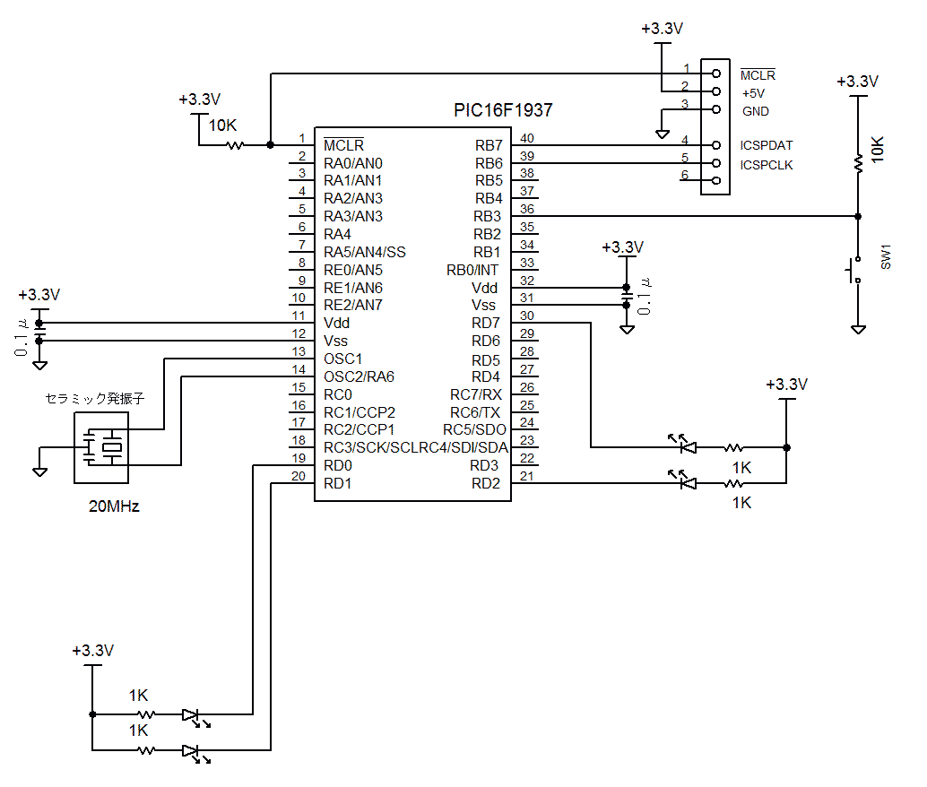
<試作品外観>下記の写真には上記回路図にはない、また本テーマと関係のない部品が多々写っています
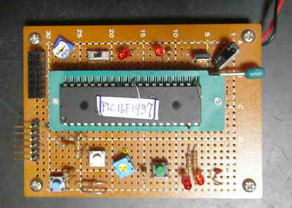
   <プログラム例>

//HI-TEC LED  Momentary SW ON_OFF
//  変化割り込み                          PIC16F1937

#include  <htc.h>

#define _XTAL_FREQ 20000000             //Ceramic :20MHz

//Configuration
__CONFIG(
                FOSC_HS &                       // EXTRC Oscillator, RC on RA7/OSC1/CLKIN
                WDTE_OFF &              // Power-up Timer Enable bit// PWRT disabled
                PWRTE_ON &              // MCLR Pin Function Select// RE3/MCLR/VPP pin function is MCLR
                MCLRE_ON &              // RE3/MCLR/VPP pin function is digital input
                CP_OFF  &               // Program memory code protection is enabled
                CPD_OFF &               // Data memory code protection is enabled
                BOREN_OFF &             // Clock Out Enable bit// CLKOUT function is disabled. I/O or oscillator function on RA6/CLKOUT
                CLKOUTEN_OFF &  // CLKOUT function is enabled on RA6/CLKOUT pin
                IESO_OFF &              // Fail Clock Monitor Enable// Fail-Safe Clock Monitor is enabled
                FCMEN_ON                // Fail-Safe Clock Monitor is disabled
                );


__CONFIG(
                WRT_OFF &       // 000h to 1FFh write protected, 200h to 1FFFh may be modified by EECON control
                PLLEN_OFF &     // 4x PLL disabled
                STVREN_OFF &// Brown-out Reset Voltage selection// Brown-out Reset Voltage (VBOR) set to 1.9 V
                BORV_19 &       // Brown-out Reset Voltage (VBOR) set to 2.7 V
//              DEBUG_OFF &     // Background debugger is enabled
                LVP_OFF         // HV on MCLR/VPP must not be used for programming
                );


short int Led = 0;       //LED mode : LED On:1 LED OFF:0

void interrupt ISR(void)
{

        IOCIE = 0;      // 状態変化イネーブルビット禁止
        PEIE = 0;       //Peripheral INT Disable
        GIE = 0;        //Gloval INT Disable

        if(IOCBF3 == 1) //RB3ポート 状態変化割り込み発生
        {
                        if(Led == 0)    //if LED Not Lighted
                        {

                        Led = 1;
                        LATD0 = 0;      //   LED: Turn on


                        }
                        else  //if LED Lighted
                        {
                        Led = 0;
                        LATD0 = 1;   //LED : Turn off

                        }


        }


        IOCIF = 0;      // 状態変化割り込みフラグを クリア
        IOCBF3 = 0;     //RB3の状態変化割り込み検出フラグをクリア
        IOCIE = 1;      // 状態変化イネーブル ビットをセット

    PEIE = 0;   // Peripheral INT Disable
    GIE = 1;    //Gloval INT Enable


/*
        INTE = 0;       //ext INT Disable
        PEIE = 0;       //Peripheral INT Disable
        GIE = 0;        //Gloval INT Disable


  if (INTF) {
    INTF = 0;  //reset intf


   RD0 = RD0 ^ 1;  //flip rd0
        //LATD0 = LATD0 ^ 1;


  }


        INTF = 0;       //INT Flag clear
        INTE = 1;       //INT Enable
    PEIE = 0;   // Peripheral INT Disable
    GIE = 1;    //Gloval INT Enable

*/


}


int main()
{
        TRISB = 0x0F;   //RB0-3: in port
        TRISD = 0;      //D port: outport

        ANSELB = 0;     //PIC16F1937 のBポートははデフォルトではアナログモードなのでデジタルモードに変換
        ANSELD = 0;     //PIC16F1937 のDポートははデフォルトではアナログモードなのでデジタルモードに変換

        IOCBN3 = 1;     //RB3ポートを 立ち下がりエッジの状態変化で割り込み発生モードにセット

        Led = 0;           //LED Mode: OFF Mode
        LATD0 = 1;        //RD0 port LED off

        IOCIF = 0;      // 状態変化割り込みフラグを クリア
        IOCBF3 = 0;     //RB3の状態変化割り込み検出フラグをクリア
        IOCIE = 1;      // 状態変化イネーブル ビットをセット

        PEIE = 0;   // Peripheral INT Disable
        GIE = 1;    // Gloval INT Enable

        while(1)
        {
        }
        return 0;
}
<PIC18>
<試作品回路図> (→回路図のPDFファイル)
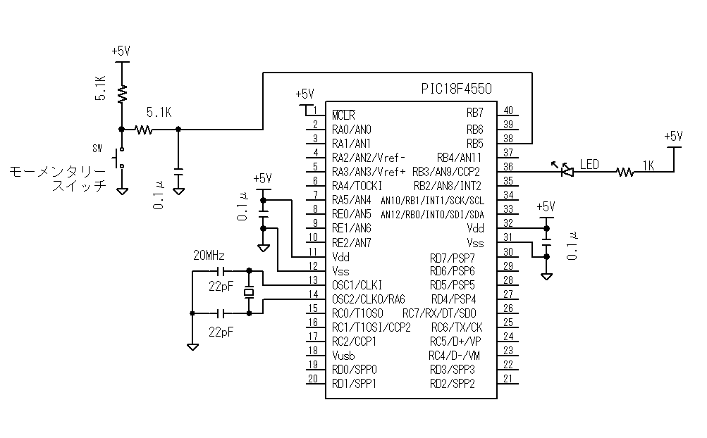
<試作品外観>下記の写真には上記回路図にはない、また本テーマと関係のない部品が多々写っています
<CCS編> ************************************************************************************
モメンタリスイッチによるLEDのON/OFF *************************************************************
<プログラム例> Bポート変化割込み
/*
オルタネートスイッチ
Bポート変化割込みによる
LED ON/OFF
*/
#include <18F4550.h>
#use delay(clock=20000000)
#FUSES HS,PUT,NOWDT,BROWNOUT,BORV43,NOPROTECT,NOLVP
int Led= 0; //LEDモード : LED点灯モード:1 消灯モード:0
int SwMode = 0; //スイッチが押されていると判断している場合:1
void SwDetect()
{
disable_interrupts(INT_RB); //チャタリングしている間割込みを禁止する
disable_interrupts(GLOBAL);
delay_ms(100); //50msecの間待つ
if(input(PIN_B5) == 0) //RB5ポートをチェックして ”0”なら
{
SwMode = 1;
if(Led == 1) //LEDが点灯していたのなら
{
Led = 0; //LEDのモードを消灯モードにセットして
output_high(PIN_B3); //RB3ポートをHigh(5v)にしてLEDを消灯する
}
else // またLEDが消灯していたなら
{
Led = 1; // LEDのモードを点灯モードにセットして
output_low(PIN_B3); // RB3ポートをLow(0v)にしてLEDを点灯する
}
}
enable_interrupts(INT_RB); //ポートBのbit4〜bit7のいずれかが high→low または low→highに変化した時に割り込みが発生
enable_interrupts(GLOBAL); // すべての割り込みを許可
}
#int_rb
void int_portB() // 外部割込み関数
{
if(SwMode == 0)SwDetect(); //スイッチが押されていないと判断している場合
if(input(PIN_B5) == 1)SwMode = 0; //RB5ポートが0(スイッチが一瞬でも離れた) なら、スイッチ検出を開始
}
void main(void)
{
enable_interrupts(INT_RB); //ポートBのbit4〜bit7のいずれかが high→low または low→highに変化した時に割り込みが発生
enable_interrupts(GLOBAL); // すべての割り込みを許可
Led = 0;
output_high(PIN_B3); //電源投入でLED消灯
while(1)
{ //割込みが発生する以外は何もしないで待つ
}
}
<C18編> ***************************************************************************************:
モメンタリスイッチによるLEDのON/OFF *************************************************************
 <プログラム例><C18編> Bポートの変化割込みによる方法

/*
オルタネートスイッチ
     変化割込みによる
                LED ON/OFF
*/
#include <p18f4550.h>
#include <portb.h>
#include <delays.h>


#pragma config PLLDIV = 5           //96MHz PLL Prescalar(1、2、3、4、5、6、10、12のみ) : 外部周波数÷4MHz
                                    //20MHz ÷ 5 = 4MHz → 96MHz(=4MHz×24 :固定)
#pragma config USBDIV = 2           // Full Speed USB Clock Source Selection : 2(constant)
#pragma config CPUDIV = OSC1_PLL2   //CPU System Clock Postscaler
                                    // PICのUSB制御用クロック周波数:48MHz(=96MHz ÷2)
#pragma config FOSC = HS            // システムクロック=20MHz
//#pragma config FOSC = HSPLL_HS    // システムクロック=48MHz

#pragma config WDT = OFF            //ウォッチドックタイマOFF
#pragma config LVP = OFF            //低電圧書き込みOFF
#pragma config PWRT = ON            //パワーアップタイマON
#pragma config BOR = ON             //ブラウンアウトリセットON(ハードウェアのみ)
#pragma config BORV = 1             //Brown out Voltage = 4.33v
                                    // ref: BORV=0 → 4.59v    BORV=2 → 2.79v  BORV=4 → 2.05v
#pragma config PBADEN = OFF         //リセットでポートBの全アナログポートをデジタルI/Oにリセット
                                    // PORTB A/D Enable bit = 0 (CONFIG3H)

void delay_ms(long int);
void int_portB();
void SwDetect();

void delay_ms (long int cycle)                        // CCSコンパイラと同じ delay_ms(long int) 関数を設計
{
        long int i = 0;
        for (i = 0; i < cycle; i++)Delay1KTCYx(5);    // 0.05μsec × 4 × 5000 = 1msec システムクロック=20Mhz
}

int Led= 0;                                           //LEDモード : LED点灯モード:1 消灯モード:0
int SwMode = 0;                                       //スイッチが押されていると判断している場合:1


void SwDetect()
{
        INTCONbits.RBIE= 0;     //変化割込みの禁止
        INTCONbits.PEIE = 0;    //低位割込み禁止
        INTCONbits.GIE = 0;     //全割込み禁止


        delay_ms(100);          //100msecの間待つ

        if(PORTBbits.RB5 == 0)  //RB5ポートをチェックして ”0”なら
        {
                SwMode = 1;
                if(Led == 1)                   //LEDが点灯していたのなら
                {
                        Led = 0;               //LEDのモードを消灯モードにセットして
                        LATBbits.LATB3 = 1;    //RB3ポートをHigh(5v)にしてLEDを消灯する
                }
                else                            // またLEDが消灯していたなら
                {
                        Led = 1;                // LEDのモードを点灯モードにセットして
                        LATBbits.LATB3 = 0;     // RB3ポートをLow(0v)にしてLEDを点灯する
                }
        }
        INTCONbits.RBIE= 1;     //変化割込みの許可
        INTCONbits.PEIE = 1;    //低位割込み許可
        INTCONbits.GIE = 1;     //全割込み許可
}


#pragma code low_vector=0x8     //高位レベル割込み
void low_interrupt (void)
{
        _asm GOTO int_portB _endasm
}
#pragma code
#pragma interruptlow int_portB
void int_portB()                          // 外部割込み関数
{
        INTCONbits.RBIF = 0;              //変化割込みのフラグをリセット
        if(SwMode == 0)SwDetect();        //スイッチが押されていないと判断している場合
        if(PORTBbits.RB5 == 1)SwMode = 0; //RB5ポートが0(スイッチが一瞬でも離れた) なら、スイッチ検出を開始
}


void main(void)
{
        TRISB = 0b11110000;                         // B portを入力モードに その他を出力モードに設定

        OpenPORTB(PORTB_CHANGE_INT_ON &             //ポートRB5の変化割込みON
                                PORTB_PULLUPS_OFF   //Bポートの抵抗プルアップOFF
                                );
        RCONbits.IPEN = 1;                          //割込み優先順位制御ON  (0:優先順位制御OFF)
        INTCON2bits.RBIP = 1;                       //変化の割り込みを高位割込みにセット(0:低位割込み)
        INTCONbits.RBIE= 1;                         //変化割込みの許可
        INTCONbits.PEIE = 1;                        //低位割込み許可
        INTCONbits.GIE = 1;                         //全割込み許可

        Led = 0;
        LATBbits.LATB3 = 1 ;                        //電源投入でLED消灯

        while(1)
        {                                           //割込みが発生する以外は何もしないで待つ
        }
}
■ 状態変化割り込み PIC32MZ編
<試作品仕様>
・RB0ピンに接続されたスイッチにより、状態変化割り込みをつかって PG15ピンのLEDをON/OFFする
<試作品回路図>(→回路図のPDFファイル)
PIC32MZ2048ECH100をつかった場合の回路図を以下に示します。
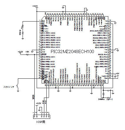
<試作品外観>下記の写真には上記回路図にはない、また本テーマと関係のない部品が多々写っています
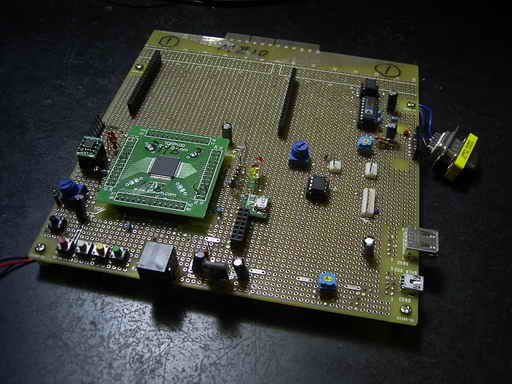
<MHC>
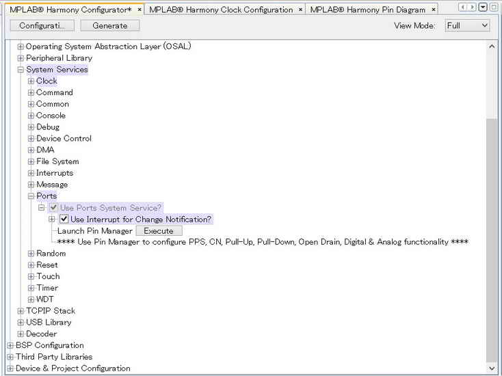 |
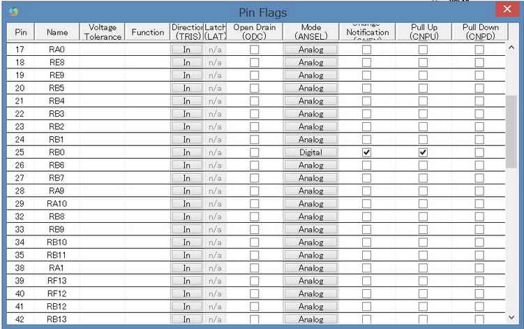 |
   <プログラム例>

//以下、main.c
//-----------------------------------------------------------------------------------------
/*******************************************************************************
  MPLAB Harmony Project Main Source File

  Company:
    Microchip Technology Inc.

  File Name:
    main.c

  Summary:
    This file contains the "main" function for an MPLAB Harmony project.

  Description:
    This file contains the "main" function for an MPLAB Harmony project.  The
    "main" function calls the "SYS_Initialize" function to initialize the state
    machines of all MPLAB Harmony modules in the system and it calls the
    "SYS_Tasks" function from within a system-wide "super" loop to maintain
    their correct operation. These two functions are implemented in
    configuration-specific files (usually "system_init.c" and "system_tasks.c")
    in a configuration-specific folder under the "src/system_config" folder
    within this project's top-level folder.  An MPLAB Harmony project may have
    more than one configuration, each contained within it's own folder under
    the "system_config" folder.
 *******************************************************************************/

// DOM-IGNORE-BEGIN
/*******************************************************************************
Copyright (c) 2013-2014 released Microchip Technology Inc.  All rights reserved.

//Microchip licenses to you the right to use, modify, copy and distribute
Software only when embedded on a Microchip microcontroller or digital signal
controller that is integrated into your product or third party product
(pursuant to the sublicense terms in the accompanying license agreement).

You should refer to the license agreement accompanying this Software for
additional information regarding your rights and obligations.

SOFTWARE AND DOCUMENTATION ARE PROVIDED "AS IS" WITHOUT WARRANTY OF ANY KIND,
EITHER EXPRESS OR IMPLIED, INCLUDING WITHOUT LIMITATION, ANY WARRANTY OF
MERCHANTABILITY, TITLE, NON-INFRINGEMENT AND FITNESS FOR A PARTICULAR PURPOSE.
IN NO EVENT SHALL MICROCHIP OR ITS LICENSORS BE LIABLE OR OBLIGATED UNDER
CONTRACT, NEGLIGENCE, STRICT LIABILITY, CONTRIBUTION, BREACH OF WARRANTY, OR
OTHER LEGAL EQUITABLE THEORY ANY DIRECT OR INDIRECT DAMAGES OR EXPENSES
INCLUDING BUT NOT LIMITED TO ANY INCIDENTAL, SPECIAL, INDIRECT, PUNITIVE OR
CONSEQUENTIAL DAMAGES, LOST PROFITS OR LOST DATA, COST OF PROCUREMENT OF
SUBSTITUTE GOODS, TECHNOLOGY, SERVICES, OR ANY CLAIMS BY THIRD PARTIES
(INCLUDING BUT NOT LIMITED TO ANY DEFENSE THEREOF), OR OTHER SIMILAR COSTS.
 *******************************************************************************/
// DOM-IGNORE-END


// *****************************************************************************
// *****************************************************************************
// Section: Included Files
// *****************************************************************************
// *****************************************************************************

#include <stddef.h>                     // Defines NULL
#include <stdbool.h>                    // Defines true
#include <stdlib.h>                     // Defines EXIT_FAILURE
#include "system/common/sys_module.h"   // SYS function prototypes


// *****************************************************************************
// *****************************************************************************
// Section: Main Entry Point
// *****************************************************************************
// *****************************************************************************

int main ( void )
{
    /* Initialize all MPLAB Harmony modules, including application(s). */
    SYS_Initialize ( NULL );


    while ( true )
    {
        /* Maintain state machines of all polled MPLAB Harmony modules. */
        SYS_Tasks ( );

    }

    /* Execution should not come here during normal operation */

    return ( EXIT_FAILURE );
}


/*******************************************************************************
 End of File
*/


//以下、app.c
//----------------------------------------------------------------------------------------
/*******************************************************************************
  MPLAB Harmony Application Source File

  Company:
    Microchip Technology Inc.

  File Name:
    app.c

  Summary:
    This file contains the source code for the MPLAB Harmony application.

  Description:
    This file contains the source code for the MPLAB Harmony application.  It
    implements the logic of the application's state machine and it may call
    API routines of other MPLAB Harmony modules in the system, such as drivers,
    system services, and middleware.  However, it does not call any of the
    system interfaces (such as the "Initialize" and "Tasks" functions) of any of
    the modules in the system or make any assumptions about when those functions
    are called.  That is the responsibility of the configuration-specific system
    files.
 *******************************************************************************/

// DOM-IGNORE-BEGIN
/*******************************************************************************
Copyright (c) 2013-2014 released Microchip Technology Inc.  All rights reserved.

Microchip licenses to you the right to use, modify, copy and distribute
Software only when embedded on a Microchip microcontroller or digital signal
controller that is integrated into your product or third party product
(pursuant to the sublicense terms in the accompanying license agreement).

You should refer to the license agreement accompanying this Software for
additional information regarding your rights and obligations.

SOFTWARE AND DOCUMENTATION ARE PROVIDED "AS IS" WITHOUT WARRANTY OF ANY KIND,
EITHER EXPRESS OR IMPLIED, INCLUDING WITHOUT LIMITATION, ANY WARRANTY OF
MERCHANTABILITY, TITLE, NON-INFRINGEMENT AND FITNESS FOR A PARTICULAR PURPOSE.
IN NO EVENT SHALL MICROCHIP OR ITS LICENSORS BE LIABLE OR OBLIGATED UNDER
CONTRACT, NEGLIGENCE, STRICT LIABILITY, CONTRIBUTION, BREACH OF WARRANTY, OR
OTHER LEGAL EQUITABLE THEORY ANY DIRECT OR INDIRECT DAMAGES OR EXPENSES
INCLUDING BUT NOT LIMITED TO ANY INCIDENTAL, SPECIAL, INDIRECT, PUNITIVE OR
CONSEQUENTIAL DAMAGES, LOST PROFITS OR LOST DATA, COST OF PROCUREMENT OF
SUBSTITUTE GOODS, TECHNOLOGY, SERVICES, OR ANY CLAIMS BY THIRD PARTIES
(INCLUDING BUT NOT LIMITED TO ANY DEFENSE THEREOF), OR OTHER SIMILAR COSTS.
 *******************************************************************************/
// DOM-IGNORE-END


// *****************************************************************************
// *****************************************************************************
// Section: Included Files
// *****************************************************************************
// *****************************************************************************

#include "app.h"

extern int ChangeFlag;
int mode = 0;
int delay_Clock = 200000000;   //200MHz

void delay_us(volatile unsigned int usec)        //1μsec遅延
{
        volatile  int count;

        count = (int)(delay_Clock/20000000)*usec;


        do      //実測 at 200MH (Clock=200000000)
        {       //delay_us(1000):1000.4μsec  delay_us(100):100.6μsec  delay_us(10):10.5μsec  delay_us(1):1.5μsec
                asm("NOP"); asm("NOP"); asm("NOP"); asm("NOP"); asm("NOP");asm("NOP");
                asm("NOP"); asm("NOP"); asm("NOP"); asm("NOP"); asm("NOP"); asm("NOP");

                count--;
        }while(count != 0);


}

void delay_ms(volatile unsigned int msec)        //1msec遅延
{
        volatile unsigned int i;         //実測:at200MH (Clock=200000000)//delay_ms(1): 1.0006msec   delay_ms(100):100.04msec

        for(i=0; i<msec; i++)
        delay_us(1000);
}


// *****************************************************************************
// *****************************************************************************
// Section: Global Data Definitions
// *****************************************************************************
// *****************************************************************************

// *****************************************************************************
/* Application Data

  Summary:
    Holds application data

  Description:
    This structure holds the application's data.

  Remarks:
    This structure should be initialized by the APP_Initialize function.

    Application strings and buffers are be defined outside this structure.
*/

APP_DATA appData;

// *****************************************************************************
// *****************************************************************************
// Section: Application Callback Functions
// *****************************************************************************
// *****************************************************************************

/* TODO:  Add any necessary callback funtions.
*/

// *****************************************************************************
// *****************************************************************************
// Section: Application Local Functions
// *****************************************************************************
// *****************************************************************************

/* TODO:  Add any necessary local functions.
*/


// *****************************************************************************
// *****************************************************************************
// Section: Application Initialization and State Machine Functions
// *****************************************************************************
// *****************************************************************************

/*******************************************************************************
  Function:
    void APP_Initialize ( void )

  Remarks:
    See prototype in app.h.
 */

void APP_Initialize ( void )
{
    /* Place the App state machine in its initial state. */
    appData.state = APP_STATE_INIT;

    /* TODO: Initialize your application's state machine and other
     * parameters.
     */

    LATGbits.LATG15 = 0;    //LED 消灯
}


/******************************************************************************
  Function:
    void APP_Tasks ( void )

  Remarks:
    See prototype in app.h.
 */

void APP_Tasks ( void )
{
    /* Check the application's current state. */
    switch ( appData.state )
    {
        /* Application's initial state. */
        case APP_STATE_INIT:
        {
            if(ChangeFlag == 1) //状態変化が発生していた場合
            {

                ChangeFlag = 0;     //状態変化フラグクリア
                if(mode == 0)
                {
                    mode = 1;
                    LATGbits.LATG15 = 0;    //LED 消灯
                }
                else
                {
                    mode = 0;
                    LATGbits.LATG15 = 1;    //LED点灯
                }
            }


            break;
        }

        /* TODO: implement your application state machine.*/

        /* The default state should never be executed. */
        default:
        {
            /* TODO: Handle error in application's state machine. */
            break;
        }
    }
}


/*******************************************************************************
 End of File
 */


//以下、system_init.c
//-------------------------------------------------------------------------------------------
/*******************************************************************************
  System Initialization File

  File Name:
    system_init.c

  Summary:
    This file contains source code necessary to initialize the system.

  Description:
    This file contains source code necessary to initialize the system.  It
    implements the "SYS_Initialize" function, configuration bits, and allocates
    any necessary global system resources, such as the systemObjects structure
    that contains the object handles to all the MPLAB Harmony module objects in
    the system.
 *******************************************************************************/

// DOM-IGNORE-BEGIN
/*******************************************************************************
Copyright (c) 2013-2014 released Microchip Technology Inc.  All rights reserved.

Microchip licenses to you the right to use, modify, copy and distribute
Software only when embedded on a Microchip microcontroller or digital signal
controller that is integrated into your product or third party product
(pursuant to the sublicense terms in the accompanying license agreement).

You should refer to the license agreement accompanying this Software for
additional information regarding your rights and obligations.

SOFTWARE AND DOCUMENTATION ARE PROVIDED AS IS WITHOUT WARRANTY OF ANY KIND,
EITHER EXPRESS OR IMPLIED, INCLUDING WITHOUT LIMITATION, ANY WARRANTY OF
MERCHANTABILITY, TITLE, NON-INFRINGEMENT AND FITNESS FOR A PARTICULAR PURPOSE.
IN NO EVENT SHALL MICROCHIP OR ITS LICENSORS BE LIABLE OR OBLIGATED UNDER
CONTRACT, NEGLIGENCE, STRICT LIABILITY, CONTRIBUTION, BREACH OF WARRANTY, OR
OTHER LEGAL EQUITABLE THEORY ANY DIRECT OR INDIRECT DAMAGES OR EXPENSES
INCLUDING BUT NOT LIMITED TO ANY INCIDENTAL, SPECIAL, INDIRECT, PUNITIVE OR
CONSEQUENTIAL DAMAGES, LOST PROFITS OR LOST DATA, COST OF PROCUREMENT OF
SUBSTITUTE GOODS, TECHNOLOGY, SERVICES, OR ANY CLAIMS BY THIRD PARTIES
(INCLUDING BUT NOT LIMITED TO ANY DEFENSE THEREOF), OR OTHER SIMILAR COSTS.
 *******************************************************************************/
// DOM-IGNORE-END


// *****************************************************************************
// *****************************************************************************
// Section: Included Files
// *****************************************************************************
// *****************************************************************************

#include "system_config.h"
#include "system_definitions.h"
#include "app.h"


// ****************************************************************************
// ****************************************************************************
// Section: Configuration Bits
// ****************************************************************************
// ****************************************************************************

//-----------------------------------------------------------------------
//DEVCFG0レジスタ
#pragma config EJTAGBEN = NORMAL
#pragma config DBGPER = ALLOW_PG2
#pragma config FSLEEP = OFF
#pragma config FECCCON = OFF_UNLOCKED
#pragma config BOOTISA = MIPS32
#pragma config TRCEN = OFF
#pragma config ICESEL = ICS_PGx2
#pragma config JTAGEN = OFF //JTAG ポート Disable
#pragma config DEBUG = OFF


//----------------------------------------------------------------------
//DEVCFG1レジスタ
#pragma config FNOSC = SPLL //PLL回路(システムPLL)選択   //システム発振回路 //内蔵FRC(8MHz)選択の場合:FNOSC = FRCDIV   //Oscillator Selection Bits (Fast RC Osc w/Div-by-N (FRCDIV))
#pragma config FDMTEN = OFF //デッドマンタイマ OFF (Deadman Timer is disabled)
//#pragma config DMTINTV = WIN_127_128 // DMT Count Window Interval (Window/Interval value is 127/128 counter value)

#pragma config FSOSCEN = OFF // 副発振器OFF   //Secondary Oscillator Enable (Disable SOSC)
#pragma config IESO = OFF //ウェイクアップ時の2段速度スタートアップ // Internal/External Switch Over (Disabled)

#pragma config POSCMOD = HS //HS: ハイスピードレゾネータモード // HS(High Speed Resonator Operation) Oscillator mode selected
                            //EC: 外部発振器    //EC(External Clock Input Operation) mode selected // Primary Oscillator Configuration (Primary osc disabled)
#pragma config OSCIOFNC = OFF //OSCCOピン出力無効
#pragma config FCKSM = CSECME   //クロック発振:切替及びモニタ有効  //主発振器失陥でFRC(内蔵高速発振器)に切替   //FSCM(Fail Safe Clock Monitor)制御

#pragma config FWDTEN = OFF // ウォッチドックタイマ OFF    //Watchdog Timer Disable
//#pragma config WDTPS = PS1048576 // Watchdog Timer Postscaler (1:1048576)
//#pragma config WDTSPGM = STOP // Watchdog Timer Stop During Flash Programming (WDT stops during Flash programming)
//#pragma config WINDIS = NORMAL // Watchdog Timer Window Mode (Watchdog Timer is in non-Window mode)
//#pragma config FWDTWINSZ = WINSZ_25 // Watchdog Timer Window Size (Window size is 25%)


//--------------------------------------------------------------------------------------------------------------------
// DEVCFG2レジスタ
//システムクロック:200MHz
//ペリフェラル周波数://default: 100MHz    //PBxDIVで8系統毎に設定変更可
//PBxDIV: PERIPHERAL BUS CLOCK DIVISOR CONTROL レジスタのPBDIV<6:0>: Peripheral Bus Clock Divisor Control ビットで設定

#pragma config FPLLRNG = RANGE_5_10_MHZ        //PLL Input周波数入力範囲設定// System PLL Input Range (5-10 MHz Input)  //8(= 24/3)MHz故
#pragma config FPLLIDIV = DIV_3 //PLL入力側での分周: 1/3  // PLL Input周波数 = 24MHz ÷ 3 = 8MHz     // System PLL Input Divider (1x Divider)

//#pragma config FPLLICLK = PLL_POSC //主発振回路選択 //内蔵FRC(8MHz)の場合はFPLLICLK = PLL_FRC//  System PLL Input Clock Selection (POSC is input to the System PLL)
#pragma config FPLLICLK = PLL_FRC   //内蔵高速発振器選択    //★★★ バグ有 主発振回路選択の時、FPLLICLK = PLL_POSCではなくFPLLICLK = PLL_FRCを選択する。(at ver.1.33 XC32)

#pragma config FPLLMULT = MUL_50 //PLL倍率:50倍 //8MHz x 50 = 400MHz  //System PLL Multiplier (PLL Multiply by 50)
#pragma config FPLLODIV = DIV_2 //PLL出力側での分周: 1/2  //システムクロック = 400MHz ÷ 2 = 200MHz


#pragma config UPLLFSEL = FREQ_24MHZ //USBのPLL入力を 24MHz→12MHzに変換 // USB PLL Input Frequency Selection (USB PLL input is 12 MHz)
#pragma config UPLLEN = ON //USBのPLL変換:イネーブル // USB PLL Enable (USB PLL is enabled)


//--------------------------------------------------------------------------------------------------------------------------
//DEVCFG3レジスタ
#pragma config USERID =     0xffff
#pragma config FMIIEN =     ON
#pragma config FETHIO =     ON
#pragma config PGL1WAY =    ON
#pragma config PMDL1WAY =   ON
#pragma config IOL1WAY =    ON
#pragma config FUSBIDIO =   ON


/*** BF1SEQ0 ***/

#pragma config TSEQ =       0xffff
#pragma config CSEQ =       0xffff


// *****************************************************************************
// *****************************************************************************
// Section: Library/Stack Initialization Data
// *****************************************************************************
// *****************************************************************************/


// *****************************************************************************
// *****************************************************************************
// Section: Driver Initialization Data
// *****************************************************************************
// *****************************************************************************


// *****************************************************************************
// *****************************************************************************
// Section: System Data
// *****************************************************************************
// *****************************************************************************

/* Structure to hold the object handles for the modules in the system. */
SYSTEM_OBJECTS sysObj;

// *****************************************************************************
// *****************************************************************************
// Section: Module Initialization Data
// *****************************************************************************
// *****************************************************************************


/*** System Device Control Initialization Data ***/

const SYS_DEVCON_INIT sysDevconInit =
{
    .moduleInit = {0},
};

// *****************************************************************************
// *****************************************************************************
// Section: Static Initialization Functions
// *****************************************************************************
// *****************************************************************************


// *****************************************************************************
// *****************************************************************************
// Section: System Initialization
// *****************************************************************************
// *****************************************************************************

/*******************************************************************************
  Function:
    void SYS_Initialize ( SYS_INIT_DATA *data )

  Summary:
    Initializes the board, services, drivers, application and other modules.

  Remarks:
    See prototype in system/common/sys_module.h.
 */

void SYS_Initialize ( void* data )
{
    /* Core Processor Initialization */
    SYS_CLK_Initialize( NULL );
    sysObj.sysDevcon = SYS_DEVCON_Initialize(SYS_DEVCON_INDEX_0, (SYS_MODULE_INIT*)&sysDevconInit);
    SYS_DEVCON_PerformanceConfig(SYS_CLK_SystemFrequencyGet());
    SYS_DEVCON_JTAGDisable();
    SYS_PORTS_Initialize();

    /* Initialize Drivers */

    /* Initialize System Services */
    SYS_INT_Initialize();

    /* Initialize Middleware */
    /* Enable Global Interrupts */
    SYS_INT_Enable();

    /* Initialize the Application */
    APP_Initialize();

}

/*******************************************************************************
 End of File
*/


//以下、system_interrupt.c
//-------------------------------------------------------------------------------------
/*******************************************************************************
 System Interrupts File

  File Name:
    system_int.c

  Summary:
    Raw ISR definitions.

  Description:
    This file contains a definitions of the raw ISRs required to support the
    interrupt sub-system.

  Summary:
    This file contains source code for the interrupt vector functions in the
    system.

  Description:
    This file contains source code for the interrupt vector functions in the
    system.  It implements the system and part specific vector "stub" functions
    from which the individual "Tasks" functions are called for any modules
    executing interrupt-driven in the MPLAB Harmony system.

  Remarks:
    This file requires access to the systemObjects global data structure that
    contains the object handles to all MPLAB Harmony module objects executing
    interrupt-driven in the system.  These handles are passed into the individual
    module "Tasks" functions to identify the instance of the module to maintain.
 *******************************************************************************/

// DOM-IGNORE-BEGIN
/*******************************************************************************
Copyright (c) 2011-2014 released Microchip Technology Inc.  All rights reserved.

Microchip licenses to you the right to use, modify, copy and distribute
Software only when embedded on a Microchip microcontroller or digital signal
controller that is integrated into your product or third party product
(pursuant to the sublicense terms in the accompanying license agreement).

You should refer to the license agreement accompanying this Software for
additional information regarding your rights and obligations.

SOFTWARE AND DOCUMENTATION ARE PROVIDED "AS IS" WITHOUT WARRANTY OF ANY KIND,
EITHER EXPRESS OR IMPLIED, INCLUDING WITHOUT LIMITATION, ANY WARRANTY OF
MERCHANTABILITY, TITLE, NON-INFRINGEMENT AND FITNESS FOR A PARTICULAR PURPOSE.
IN NO EVENT SHALL MICROCHIP OR ITS LICENSORS BE LIABLE OR OBLIGATED UNDER
CONTRACT, NEGLIGENCE, STRICT LIABILITY, CONTRIBUTION, BREACH OF WARRANTY, OR
OTHER LEGAL EQUITABLE THEORY ANY DIRECT OR INDIRECT DAMAGES OR EXPENSES
INCLUDING BUT NOT LIMITED TO ANY INCIDENTAL, SPECIAL, INDIRECT, PUNITIVE OR
CONSEQUENTIAL DAMAGES, LOST PROFITS OR LOST DATA, COST OF PROCUREMENT OF
SUBSTITUTE GOODS, TECHNOLOGY, SERVICES, OR ANY CLAIMS BY THIRD PARTIES
(INCLUDING BUT NOT LIMITED TO ANY DEFENSE THEREOF), OR OTHER SIMILAR COSTS.
 *******************************************************************************/
// DOM-IGNORE-END


// *****************************************************************************
// *****************************************************************************
// Section: Included Files
// *****************************************************************************
// *****************************************************************************

#include <xc.h>
#include <sys/attribs.h>
#include "app.h"
#include "system_definitions.h"


int ChangeFlag= 0;  //RB01の状態変化フラグ


// *****************************************************************************
// *****************************************************************************
// Section: System Interrupt Vector Functions
// *****************************************************************************
// *****************************************************************************
void __ISR(_CHANGE_NOTICE_B_VECTOR, ipl1AUTO) _IntHandlerChangeNotification_PortB(void)
{
    if(PORTBbits.RB0 == 0)ChangeFlag = 1;


    PLIB_INT_SourceFlagClear(INT_ID_0,INT_SOURCE_CHANGE_NOTICE_B);  //フラグクリア


}

/*******************************************************************************
 End of File
*/


//以下、sys_ports_static.c
//------------------------------------------------------------------------------------
/*******************************************************************************
  SYS PORTS Static Functions for PORTS System Service

  Company:
    Microchip Technology Inc.

  File Name:
    sys_ports_static.c

  Summary:
    SYS PORTS static function implementations for the Ports System Service.

  Description:
    The Ports System Service provides a simple interface to manage the ports
    on Microchip microcontrollers. This file defines the static implementation for the
    Ports System Service.

  Remarks:
    Static functions incorporate all system ports configuration settings as
    determined by the user via the Microchip Harmony Configurator GUI.  It provides
    static version of the routines, eliminating the need for an object ID or
    object handle.

*******************************************************************************/

//DOM-IGNORE-BEGIN
/*******************************************************************************
Copyright (c) 2013 released Microchip Technology Inc.  All rights reserved.

Microchip licenses to you the right to use, modify, copy and distribute
Software only when embedded on a Microchip microcontroller or digital signal
controller that is integrated into your product or third party product
(pursuant to the sublicense terms in the accompanying license agreement).

You should refer to the license agreement accompanying this Software for
additional information regarding your rights and obligations.

SOFTWARE AND DOCUMENTATION ARE PROVIDED AS IS WITHOUT WARRANTY OF ANY KIND,
EITHER EXPRESS OR IMPLIED, INCLUDING WITHOUT LIMITATION, ANY WARRANTY OF
MERCHANTABILITY, TITLE, NON-INFRINGEMENT AND FITNESS FOR A PARTICULAR PURPOSE.
IN NO EVENT SHALL MICROCHIP OR ITS LICENSORS BE LIABLE OR OBLIGATED UNDER
CONTRACT, NEGLIGENCE, STRICT LIABILITY, CONTRIBUTION, BREACH OF WARRANTY, OR
OTHER LEGAL EQUITABLE THEORY ANY DIRECT OR INDIRECT DAMAGES OR EXPENSES
INCLUDING BUT NOT LIMITED TO ANY INCIDENTAL, SPECIAL, INDIRECT, PUNITIVE OR
CONSEQUENTIAL DAMAGES, LOST PROFITS OR LOST DATA, COST OF PROCUREMENT OF
SUBSTITUTE GOODS, TECHNOLOGY, SERVICES, OR ANY CLAIMS BY THIRD PARTIES
(INCLUDING BUT NOT LIMITED TO ANY DEFENSE THEREOF), OR OTHER SIMILAR COSTS.
*******************************************************************************/
//DOM-IGNORE-END

#include "system_config.h"
#include "peripheral/ports/plib_ports.h"
#include "peripheral/int/plib_int.h"


void SYS_PORTS_Initialize(void)
{

    /* PORT B Initialization */
    PLIB_PORTS_DirectionOutputSet( PORTS_ID_0, PORT_CHANNEL_B,  SYS_PORT_B_TRIS ^ 0xFFFF);  //Bポート出力モード
    PLIB_PORTS_Toggle( PORTS_ID_0, PORT_CHANNEL_B,  SYS_PORT_B_LAT);
    PLIB_PORTS_OpenDrainEnable(PORTS_ID_0, PORT_CHANNEL_B, SYS_PORT_B_ODC);
    PLIB_PORTS_ChangeNoticePerPortTurnOn(PORTS_ID_0, PORT_CHANNEL_B);
    PLIB_PORTS_ChannelModeSelect(PORTS_ID_0, PORT_CHANNEL_B, SYS_PORT_B_ANSEL ^ 0xFFFF, PORTS_PIN_MODE_DIGITAL);    //Bポートデジタルモード
    PLIB_PORTS_ChannelChangeNoticeEnable(PORTS_ID_0, PORT_CHANNEL_B, SYS_PORT_B_CNEN);      //Bポート状態変化割り込み ON
    PLIB_PORTS_ChannelChangeNoticePullUpEnable(PORTS_ID_0, PORT_CHANNEL_B, SYS_PORT_B_CNPU);    //Bポートプルアップ
    PLIB_PORTS_ChannelChangeNoticePullDownEnable(PORTS_ID_0, PORT_CHANNEL_B, SYS_PORT_B_CNPD);
    PLIB_INT_SourceEnable(INT_ID_0, INT_SOURCE_CHANGE_NOTICE_B);
    PLIB_INT_VectorPrioritySet(INT_ID_0, INT_VECTOR_CHANGE_NOTICE_B, INT_PRIORITY_LEVEL1);
    PLIB_INT_VectorSubPrioritySet(INT_ID_0, INT_VECTOR_CHANGE_NOTICE_B, INT_SUBPRIORITY_LEVEL0);

    TRISGbits.TRISG15 = 0;  //RG15出力モード


    /* PPS Input Remapping */

    /* PPS Output Remapping */


}


/*******************************************************************************
 End of File
*/
<動作結果>
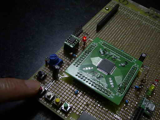
(5) 外部割り込みとタイマ割り込みを同時に使う多重割り込みによる方法
2つの割り込みに優先順位はつけない場合です。
<試作品仕様>
・INT0 と タイマ1の割り込みを併用すること
・2つの割り込みに優先順位はつけないものとする。
・ボタンスイッチSW1はINT0の外部割り込みで検出されるスイッチとして、これを押すとLEDが点灯と消灯をくりかえすこと
・ボタンスイッチSW2とSW3はタイマ1の割り込みで検出されるスイッチとし、それぞれのSWに対応してLEDが点灯と消灯をくりかえすこと
<試作品回路図>(→回路図のPDFファイル)
PIC18F87K90をつかった場合の回路図を以下に示します。
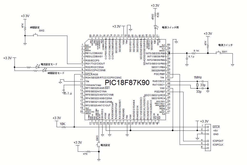
<試作品外観> 下記の写真には上記回路図にはない、また本テーマと関係のない部品も多々写っています
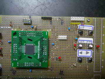
   <プログラム例>
#include <p18f87K90.h>

#include <stdio.h>
#include <delays.h>
#include <timers.h>

#define TimeLed                 LATGbits.LATG3  //時間設定モード
#define CurrentLed              LATGbits.LATG2  //電流設定モードLED

#define PowerSw                 LATBbits.LATB0          //電源スイッチ
#define TimeSetSw               PORTGbits.RG1           //時間設定スイッチ
#define CurrentSetSw    PORTFbits.RF1           //電流設定スイッチ

#pragma config FOSC = XT
#pragma config XINST = OFF
#pragma config  WDTEN = OFF     //configではウォッドックタイマOFF


unsigned char PowerMode = 0,TimeMode = 0,CurrentMode = 0;
unsigned int Count_SwTime = 0,Count_SwCurrent = 0;


const long unsigned     N_EndChat = 4;  //チャタリング終了待ち回数


void Interval(void);    //25msec タイマ1割り込み
void int0_RB0(void);    //INT0外部割り込み
void total_INT(void);   //割り込み全体


void delay_ms (unsigned long int cycle)  //msec遅延関数
{
                unsigned long int i = 0;
       for (i = 0; i < cycle; i++)Delay10TCYx(25);      //  25 x 40μsec = 1000μsec // Delay10TCY():40μsec
                                                                                                        // 実測 20%程度遅延時間大
}


void SwCheck(void)      //スイッチSW1-SW6 の検出
{
//時間設定スイッチ検出
        if((TimeSetSw == 0) && (PowerMode == 1))Count_SwTime++; //スタートスイッチ検出
        else Count_SwTime = 0;
        if(Count_SwTime == N_EndChat)   //100msec
        {
                        if(TimeMode == 0)
                        {
                                TimeMode = 1;           //時間設定モードON
                                TimeLed = 1; //時間設定モードLED点灯
                        }
                        else
                        {
                                TimeMode = 0;           //
                                TimeLed = 0;     //時間設定LED消灯
                        }
        }
        if(Count_SwTime >= (N_EndChat+1))Count_SwTime = (N_EndChat+1);  //スイッチが押され続けた場合

//電流設定スイッチ検出
        if((CurrentSetSw == 0) && (PowerMode == 1))Count_SwCurrent++;   //スタートスイッチ検出
        else Count_SwCurrent = 0;
        if(Count_SwCurrent == N_EndChat)        //100msec
        {
                        if(CurrentMode == 0)
                        {
                                CurrentMode = 1;        //電流設定モード
                                CurrentLed = 1; //電流設定LED点灯
                        }
                        else
                        {
                                CurrentMode = 0;        //ストップ
                                CurrentLed = 0;     //電流設定LED消灯
                        }
        }
        if(Count_SwCurrent >= (N_EndChat+1))Count_SwCurrent = (N_EndChat+1);    //スイッチが押され続けた場合
}


#pragma code low_vector=0x08  //割込み
void low_interrupt (void)
{
        _asm goto total_INT _endasm
}
#pragma code
#pragma interruptlow total_INT
void total_INT()
{
        if(INTCONbits.INT0IF == 1)int0_RB0();   //INT0(RB0)外部割込みの場合
        if(PIR1bits.TMR1IF == 1)Interval();     //タイマ1の割り込みの場合
}

#pragma code
void int0_RB0(void)                // 外部INT0割込み関数       //電源スイッチ、ウェイクスイッチ
{
        INTCONbits.INT0IF = 0;              //変化割込みのフラグをリセット

        if(PORTBbits.RB0 == 0)  //RB0ポートをチェックして0なら
        {
                delay_ms(50);

                if(PowerMode == 0)
                {
                        PowerMode = 1;  //電源ON
                        LATJbits.LATJ0 = 1 ;    //電源用LED ON
                }
                else
                {
                        PowerMode = 0;  //電源OFF
                        LATJbits.LATJ0 = 0 ;    //電源用LED ON
                }
        }
}


void Interval(void)     //タイマ1 25msec インターバル割り込み
{
        PIR1bits.TMR1IF = 0;    // タイマ1割り込みフラグをクリアする
        WriteTimer1(0xE805);            //1μsec × 4 × 1 × 6250 = 25000μsec = 25msec (at クロック1MHz)
                                                        //256*256 - 6250 = 59286        = 0xE796(計算値)
                                                        //実測補正後 0xE805
        SwCheck();      //SW1-SW6 のチェック
}


void main (void)
{
        ANCON0 = 0;     //ポートの初期化に必須
        ANCON1 = 0;     //ポートの初期化に必須
        ANCON2 = 0;     //ポートの初期化に必須


        TRISGbits.TRISG1 = 1;   //時間sw
        TRISGbits.TRISG2 = 0;
        TRISGbits.TRISG3 = 0;


        TRISJbits.TRISJ0  = 0;

        TRISBbits.TRISB0 = 1;   //INT0  電源スイッチ検出//ウェークアップSW
//      TRISEbits.TRISE2 = 1;   //上限電流切換え
        TRISFbits.TRISF1 = 1;   //電流設定SW

//タイマ1の設定
        T1CONbits.TMR1CS1 = 0;  //クロックソース: Fosc/4  ////Fosc: at TMRCS1 = 0, TMRCS0 = 1;
        T1CONbits.TMR1CS0 = 0;
        T1CONbits.RD16 = 1;     //Read/Write モード: 16bit
        T1CONbits.T1CKPS1 = 0;  //プリスケーラ=1/1  ////1/8 T1CKPS1 = 1;T1CONbits.T1CKPS0 = 1;
        T1CONbits.T1CKPS0 = 0;
        T1CONbits.TMR1ON = 1;   //Timer1 ON

// INT0 外部割り込み設定
        INTCON2bits.INTEDG0 = 0;        //INT0外部割込み: 立下りエッジ

        WriteTimer1(0xE805);

        PowerMode = 1;
        TimeMode = 0;           //
        TimeLed = 0;     //時間設定LED消灯
        CurrentMode = 0;
        CurrentLed = 0;
        LATJbits.LATJ0 = 1;


        RCONbits.IPEN = 0;              //割込み優先順位制御:OFF (RCON レジスタのIPENビット 0)
        INTCONbits.INT0IE= 1;   //INT0外部割込みの許可
        PIE1bits.TMR1IE = 1;    //タイマ1割込み許可
        INTCONbits.PEIE =1;             //周辺割込み許可//割り込み優先順位無の場合: RCONbits.IPEN = 0;
        INTCONbits.GIE = 1;             //全割込み許可 //割り込み優先順位無の場合: RCONbits.IPEN = 0;

         while (1)
    {                   //割り込み待ち
        }


}
(6) 外部割り込みとタイマ割り込みを同時に使う多重割り込みによる方法
2つの割り込みに優先順をつけた場合です。
<試作品仕様>
・INT0 と タイマ1の割り込みを併用すること
・INT0の割り込みはタイマ1の割り込みより高い優先順位とする。
・ボタンスイッチSW1はINT0の外部割り込みで検出されるスイッチとして、これを押すとLEDが点灯と消灯をくりかえすこと
・ボタンスイッチSW2とSW3はタイマ1の割り込みで検出されるスイッチとし、それぞれのSWに対応してLEDが点灯と消灯をくりかえすこと
<試作品回路図>(→回路図のPDFファイル)
PIC18F87K90をつかった場合の回路図を以下に示します。
<試作品外観> 下記の写真には上記回路図にはない、また本テーマと関係のない部品も多々写っています
   <プログラム例>
#include <p18f87K90.h>

#include <stdio.h>
#include <delays.h>
#include <timers.h>

#define TimeLed                 LATGbits.LATG3  //時間設定モード
#define CurrentLed              LATGbits.LATG2  //電流設定モードLED

#define PowerSw                 LATBbits.LATB0          //電源スイッチ
#define TimeSetSw               PORTGbits.RG1           //時間設定スイッチ
#define CurrentSetSw    PORTFbits.RF1           //電流設定スイッチ

#pragma config FOSC = XT
#pragma config XINST = OFF
#pragma config  WDTEN = OFF     //configではウォッドックタイマOFF


unsigned char PowerMode = 0,TimeMode = 0,CurrentMode = 0;
unsigned int Count_SwTime = 0,Count_SwCurrent = 0;


const long unsigned     N_EndChat = 4;  //チャタリング終了待ち回数


void int0_RB0(void);
void Interval(void);

void isr(void);
void tmr1(void);

void delay_ms (unsigned long int cycle)  //msec遅延関数
{
                unsigned long int i = 0;
       for (i = 0; i < cycle; i++)Delay10TCYx(25);      //  25 x 40μsec = 1000μsec // Delay10TCY():40μsec
                                                                                                        // 実測 20%程度遅延時間大
}


void SwCheck(void)      //スイッチSW1-SW2 の検出
{
//時間設定スイッチ検出
        if(TimeSetSw == 0)Count_SwTime++;       //スタートスイッチ検出
        else Count_SwTime = 0;
        if(Count_SwTime == N_EndChat)   //100msec
        {
                        if(TimeMode == 0)
                        {
                                TimeMode = 1;           //時間設定モードON
                                TimeLed = 1; //時間設定モードLED点灯
                        }
                        else
                        {
                                TimeMode = 0;           //
                                TimeLed = 0;     //時間設定LED消灯
                        }
        }
        if(Count_SwTime >= (N_EndChat+1))Count_SwTime = (N_EndChat+1);  //スイッチが押され続けた場合

//電流設定スイッチ検出
        if(CurrentSetSw == 0)Count_SwCurrent++; //スタートスイッチ検出
        else Count_SwCurrent = 0;
        if(Count_SwCurrent == N_EndChat)        //100msec
        {
                        if(CurrentMode == 0)
                        {
                                CurrentMode = 1;        //電流設定モード
                                CurrentLed = 1; //電流設定LED点灯
                        }
                        else
                        {
                                CurrentMode = 0;        //ストップ
                                CurrentLed = 0;     //電流設定LED消灯
                        }
        }
        if(Count_SwCurrent >= (N_EndChat+1))Count_SwCurrent = (N_EndChat+1);    //スイッチが押され続けた場合
}

//割込みの宣言 優先順位使用
#pragma interrupt int0_RB0
#pragma interruptlow Interval
#pragma code isrcode = 0x8
void isr_direct(void)
{
    _asm
        goto int0_RB0
    _endasm
}
#pragma code lowcode = 0x18
void low_direct(void)
{   _asm
        goto Interval
    _endasm
}

//高レベル 割込み処理関数
#pragma code
void int0_RB0(void)     // INT0割り込み
{
        delay_ms(50);
        LATJbits.LATJ0 = 0 ;    //電源用LED ON
        LATJbits.LATJ0 = 0 ;    //電源用LED ON
        INTCONbits.INT0IF = 0;  //INT0IF: b1 割込みのフラグをリセット
        LATJbits.LATJ0 = 1 ;    //電源用LED ON

        if(PORTBbits.RB0 == 0)  //RB0ポートをチェックして0なら
        {
                if(PowerMode == 0)
                {
                        PowerMode = 1;  //電源ON
                        LATJbits.LATJ0 = 1 ;    //電源用LED ON
                }
                else
                {
                        PowerMode = 0;  //電源OFF
                        LATJbits.LATJ0 = 0 ;    //電源用LED ON
                }
        }
}

//低レベル割込み処理関数
void Interval(void) // 割り込み関数
{
        PIR1bits.TMR1IF = 0;    // タイマ1割り込みフラグをクリアする
        WriteTimer1(0xE805);            //1μsec × 4 × 1 × 6250 = 25000μsec = 25msec (at クロック1MHz)
                                                        //256*256 - 6250 = 59286        = 0xE796(計算値)
                                                        //実測補正後 0xE805
        SwCheck();      //SW1-SW6 のチェック

}


void main (void)
{
        ANCON0 = 0;     //ポートの初期化に必須
        ANCON1 = 0;     //ポートの初期化に必須
        ANCON2 = 0;     //ポートの初期化に必須

        TRISGbits.TRISG1 = 1;   //時間sw
        TRISGbits.TRISG2 = 0;
        TRISGbits.TRISG3 = 0;

        TRISJbits.TRISJ0  = 0;

        TRISBbits.TRISB0 = 1;   //INT0  電源スイッチ検出//ウェークアップSW
//      TRISEbits.TRISE2 = 1;   //上限電流切換え
        TRISFbits.TRISF1 = 1;   //電流設定SW

//タイマ1の設定
        T1CONbits.TMR1CS1 = 0;  //クロックソース: Fosc/4  ////Fosc: at TMRCS1 = 0, TMRCS0 = 1;
        T1CONbits.TMR1CS0 = 0;
        T1CONbits.RD16 = 1;     //Read/Write モード: 16bit
        T1CONbits.T1CKPS1 = 0;  //プリスケーラ=1/1  ////1/8 T1CKPS1 = 1;T1CONbits.T1CKPS0 = 1;
        T1CONbits.T1CKPS0 = 0;
        T1CONbits.TMR1ON = 1;   //Timer1 ON

// INT0 外部割り込み設定
        INTCON2bits.INTEDG0 = 0;        //INT0外部割込み: 立下りエッジ

        WriteTimer1(0xE805);

        PowerMode = 1;
        TimeMode = 0;           //
        TimeLed = 0;     //時間設定LED消灯
        CurrentMode = 0;
        CurrentLed = 0;
        LATJbits.LATJ0 = 1;

    RCONbits.IPEN=1; // 優先順位割込み使用宣言
    IPR1bits.TMR1IP=0;//タイマ1を低レベル優先度にセット

        INTCONbits.INT0IE= 1;   //INT0外部割込みの許可
        PIE1bits.TMR1IE = 1;    //タイマ1割込み許可

        //割込み許可
    INTCONbits.GIEH=1;          // 高レベル許可
    INTCONbits.GIEL=1;          // 低レベル許可

         while (1)
    {                   //割り込み待ち
        }


}